| See Final Update | Solar Documents |
With the deck complete, we installed a solar power system. We aren't off-grid; we do sell excess solar power to the utility.
Scroll down to see day-by-day progress, or click the left blue button above to see the final update.
This project is complete! Solar energy now helps power much of our house.
At the request of several people, Mike wrote a book on how to plan a solar power system, based on our experience building our own. The book is freely available as a 129-page, 4.7 MB PDF file that you can download here. Click and the file opens in a new browser window. Better-still, right-click to save the PDF file to your hard drive where you can read it at your leisure. You will need Adobe Acrobat Reader.
I will appreciate it if you to say how you like the book. Thanks.
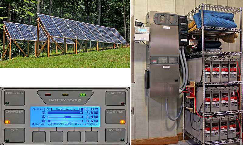
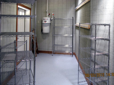
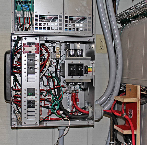
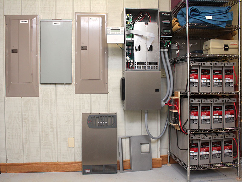
This photo shows the solar panels, the equipment and batteries inside the house, and a closeup of the system controller. Its screen shows the solar panels producing 3.8 KW of power (top bar graph), some of which is powering the 0.6 KW house loads, (bottom bar). The center bar indicates that the system is selling 2.4 KW to the utility. If the HVAC were running, it would cut the "selling" to zero, but still would run entirely on solar power.
Solar energy production needs sunny days, and varies with the season. The system has averaged 10.2 KWH per day aince it was comissioned in fall 2012. The best harvest occurred on the 2013 spring equinox, when the system produced 23.2 KWH.
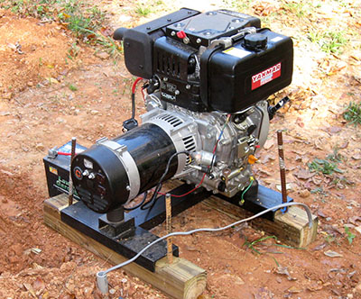
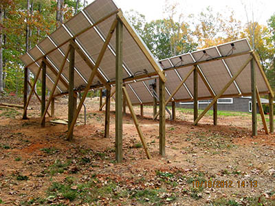
Four KW of photovoltaic (PV) panels will be installed in two rows along the north side of the septic field clearing. Twelve large batteries and an 8 KW inverter will be installed next to the electrical panels in our yard equipment room. A 6 KW diesel generator fed by a 250-gallon tank will be available to charge the batteries on days when the grid is down and the sun doesn't shine.
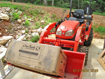
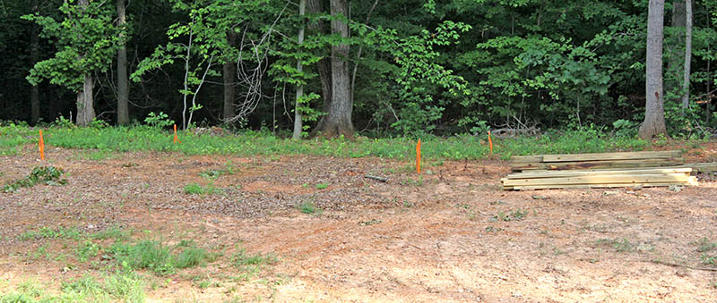
We bought a trailer-load of framing lumber and hardware for the PV panels and the diesel fuel tank support. This photo shows the lumber lying next to the PV panel site, marked with four orange ribbons.
Early-on, we concluded that we need to know how much solar power we can expect, given our location in the middle of a forest, so Mike wrote a computer program to help with this.
The Sun Angle Calculator (SAC) graphs the local horizon, the hourly sun positions, and the PV power produced during each hour, and also lists month-by-month hourly data. In addition, SAC can find the optimal PV panel orientation and sequentially graph all 12 months for easy visualization of performance over the year.
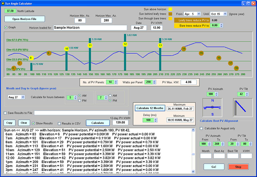
Free software! We found SAC to be very useful, and are making it freely available to everyone.
First read the user manual to learn about the program (click to read it online or right-click and save to your hard drive to read it offline).
Next, download the program ZIP file and save it to your hard drive. Unzip it to copy the SAC executable and PDF user manual, plus a couple of sample horizon files, to a folder on your hard drive. Note: You will need the Microsoft DotNet Framework 4 Client Profile installed on your Windows PC. Click this link or see page 2 in the user manual for information about this.
The PV panels were delivered, along with most of the equipment. Here are the 14 panels stacked in our driveway loop.
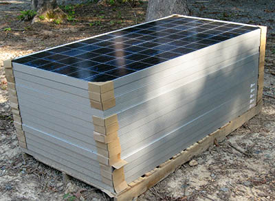
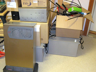
Yesterday the 12th and final battery was delivered (one was lost in the original shipment), and today UPS brought the 8 KW inverter. We now have all the equipment (Oops! Except for a missing wall-mounting plate for the inverter), and are ready to proceed.
|
|
|
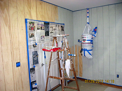
The next task is painting the yard equipment room where the equipment will live. This was deferred for 18 months, as we set up the new house and built the deck.
Yesterday and today Louise painted the yard equipment room, which is where the electrical panels are located, and where the solar power batteries and inverter will be installed. Tomorrow she will prepare the concrete floor for a coat of epoxy paint.
Yesterday Louise scrubbed and etched the concrete floor in the yard equipment room, in preparation for a coat of epoxy paint. After spending the night and all day today with a dehumidifier, the floor looks fairly dry, but we'll let the dehumidifier run overnight to be sure it's dry enough to paint.
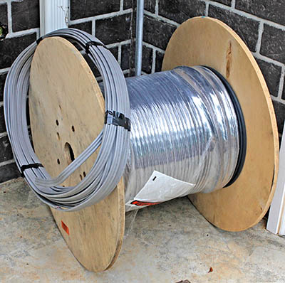
Today Mike picked up 200' of 8/2 underground feeder cable needed to run from the PV array to the house, and 75' of 10/3 from the diesel generator to the house.
OOPS! Recalculating voltage drop revealed that the power loss in #8 cable was too high, so two weeks later we bought #2 cable, and sold the #8.
With the yard equipment room painted, we began setting it up. First we installed two 8' tool racks on one wall, then we moved-in some new steel shelving. The large unit in the left foreground will hold the 12 batteries for the solar power system on the lower three shelves, leaving the top three available for general storage. The other shelving units are for landscaping, tractor, and automotive supplies.
In addition, the missing wall-mounting plate for the inverter was delivered today, so we can begin installing the equipment any time.
Our electrician stopped by today to determine why the generator won't power the well pump. It turned out that a circuit breaker on the generator feeding one leg of the 240V was tripped – easily fixed.
While the electrician was here, Mike outlined the solar equipment installation, and asked for expert opinions and advice about wiring it. He gave us valuable information, and we now have a solid plan in mind.
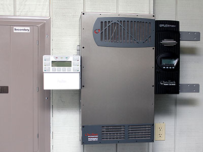
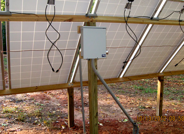
Later, Mike, Louise, and Miranda hung the Outback Power Radian inverter on the wall next to the "secondary" power panel to which it will supply power. Mike then installed the system controller and battery charge controller. The inverter is shown in this photo, with the system controller on the left side, and the charge controller on the right.
Mike made good progress installing equipment today. After drilling holes for cables that will run behind the wall and into the load center, he mounted the load center beneath the inverter. Next, he positioned the battery rack (shelf unit) and secured it to the wall to prevent tipping. Then he bolted homemade "terminal blocks" to the battery rack's sides. Finally, he moved four batteries to the lower shelf.
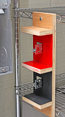
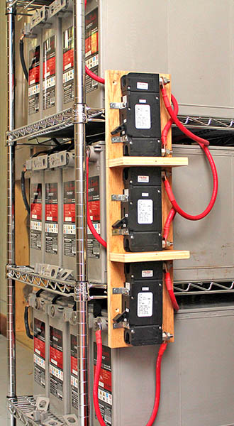
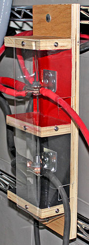
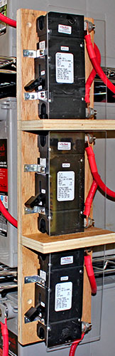
The left photo shows the block where all positive (red) and negative (black) cables will be bolted together to connect the batteries to the load center. In the center is the block holding three 175-amp circuit breakers. Cables from the battery banks' positive terminals will connect to the breakers. Cables from their outputs will run to the red block on the left.
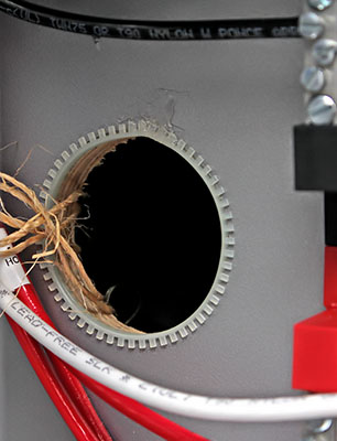
The photo on the far right shows the 2" hole in the rear panel of the load center and through the T1-11 wall paneling to allow electrical cables from the house breaker boxes, the PV array, and the diesel generator to enter the load center. We are fortunate that this path behind the wall eliminates the need to run conduit through the wall and into the load center.
|
|
|
In the evening, Mike, Louise, and Miranda placed the remaining eight batteries on two shelves. Each battery weighs 135 pounds, so one shelf is holding 540 pounds, and the entire rack is supporting 1,620 pounds. It's a good thing the shelves are rated for 800 pounds apiece!
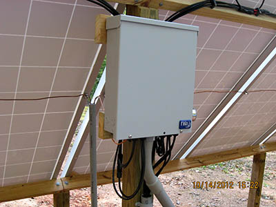
Oh my! Last night we discovered that Outback Power had packed the wrong load center in the carton, so the one we have is missing some vital parts and wiring. Fortunately, today our vendor, The altE Store, got on the phone with the manufacturer, and convinced them to ship out the correct load center. We should be able to continue installing the equipment next week. The load center is the open box beneath the inverter, with wires hanging out (photo below). It is "connection central," where all of the system components are wired together.
The replacement load center arrived today, and this evening Mike and Miranda mounted it beneath the inverter.
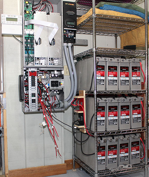
The righthand picture below (August 21) shows the Radian inverter with the black charge controller on the right side, and the load center beneath. The loaded battery rack to the right has three additional high shelves to store yard equipment and supplies.
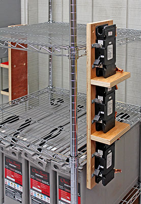
Yesterday we fabricated and installed nine #2 gauge cables for the battery bank. On the positive side of the batteries, three equal-length red cables run to three circuit breakers, and then three more equal-length red cables run to a common tie point. On the negative side, three equal-length black cables run directly to another common tie point.
A note: All three cables in a set were cut to the same length to ensure that all three battery strings are charged equally. If the cables were unequal, slight differences in their resistance would cause the battery strings to discharge and recharge unequally. For example, the battery string with the shortest cable (lowest resistance) would discharge faster than the others.
This morning we installed flexible conduit between the load center and the charge controller. Later, Mike mounted the communications hub on the left side of the load center, and ran cables to it from four pieces of equipment.
|
|
Yesterday we connected the DC (PV and battery) cables from the load center circuit breakers to the charge controller. Even though the load center is factory-wired, these cables were too short. They were cut to reach the charge controller mounted on the side of the load center, not the optional higher location on the side of the Radian inverter, where we put it.
We thought this strange because Outback Power provides mounting holes on the side of the Radian inverter for the charge controller, and the inverter installation instructions say to mount it there. In any case, we made new cables to replace the short ones.
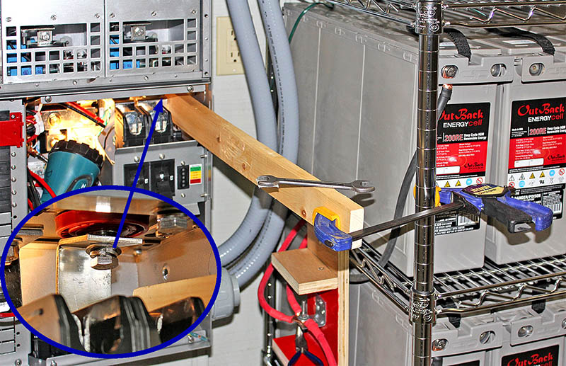
Today we connected the battery bus bars in the load center to the terminals on the bottom of the Radian inverter. This turned out to be a struggle. After the first three bolts went in easily, the holes for the fourth bolt didn't line up. We worked for an hour-and-a-half, but the bus bar wouldn't move enough. Finally Mike used a wooden 1x3 to pry it over, squeezed his hands into the tight space, and used an open-end wrench to turn the bolt enough to just catch a thread. After that, it was easy to tighten the bolt.
This photo shows the overall arrangement; the inset shows where the bolt was installed. It figures that the tightest space is the one where the holes didn't line up.
We checked-out the factory wiring in the load center to verify that the bypass interlock works, and that there are no short-circuits. Then we pulled the factory wires into the Radian inverter and connected them (upper-left). Next we cut to length the 2/0 gauge cables that connect the battery bank to the load center, and crimped terminal lugs onto their ends. Then we installed those cables (lower-right).
We've been sitting on our hands for a week, waiting for the county plan reviewer to return from vacation today. We want to have the required electrical permit in hand, even though we could build the PV panel mounting frame without it (the permit covers only the electrical wiring). We just don't want to start the outdoor work until we have the pemit.
In the meantime, Mike made plastic shields for the blocks where battery cables are bolted together to connect the batteries to the load center.
|
 |
Mike picked up the permit from the county office, so now we can proceed – once we get some dry weather.
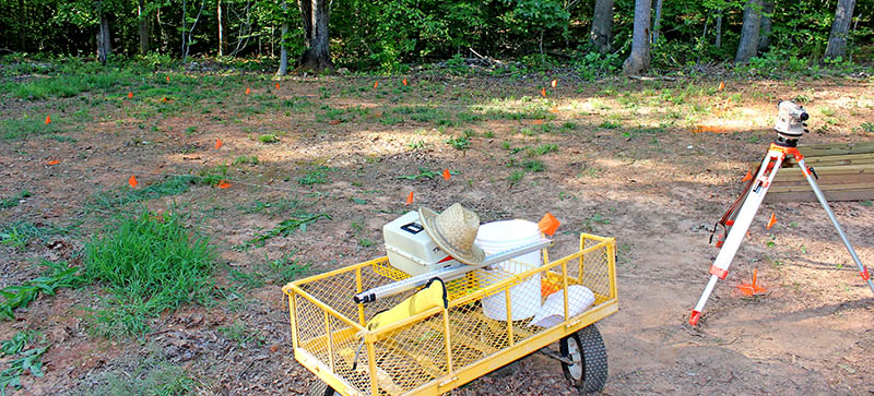
With the weather forecast showing no rain for the week, we decided to begin the outdoor work. We set up our theodolite and used it to locate the positions of support posts for the PV array, and to "shoot" grades to determine the contour of the land, so we know how long to cut the 4x4 posts.
This photo shows the theodolite and (barely visible) the orange flags marking the post locations. Tomorrow we hope to rent a trencher to dig the trench for the electrical cables.
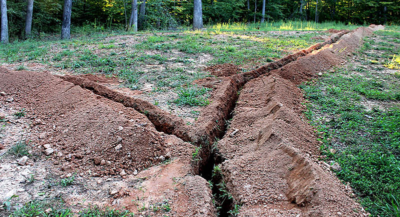
Yesterday we rented a walk-behind trenching machine and spent the afternoon and evening digging most of a 175' 18"-deep trench from the PV array area to the yard equipment room on the south side of the house. This morning we finished the main trench and dug a short branch to the generator's future location, then returned the trenching machine.
Here is the the main trench running toward the PV area in the distance, with the generator trench joining from the left.
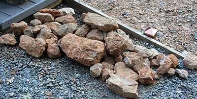
The rocks shown below are only the large ones we excavated while digging the trench. The machine stalled when it encountered one of these brutes, so we had to dig them out using hand tools. We left dozens of smaller rocks by the side of the trench, ready to be backfilled along with the dirt.
Make no mistake – digging the trench was a major effort. But it is also a significant milestone. Once the trench is inspected, we can backfill it and begin constructing the PV panel support frames.
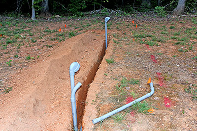
Mike measured, cut, and placed 1¼" PVC conduit in the PV trench at PV array location and at the house. Only the generator conduit remains to be placed.
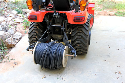
Later Mike cut-down the diameter of the wooden spool holding the #2 cable for the PV feeds, so the spool would fit on the tractor's three-point hitch, for easy unrolling. We need to cut four 200' lengths, so unrolling from the tractor will save a lot of work.
|
 |
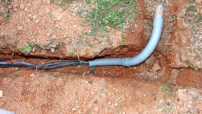
Today we spent six hours laying cable in the trenches and pulling it into the equipment room through 2" conduit. When that was done, we spread plastic sheeting over the dirt excavated from the trenches, because rain is forecast for the next few days. We'd like to have dry dirt to push back into the trenches, even if the trenches themselves have water in them.
|
|
The county inspector looked at our cables and trench, and gave us a passing grade. She also listened to Mike explain the solar power system configuration and details, then offered several tips that will help as we finish the system.
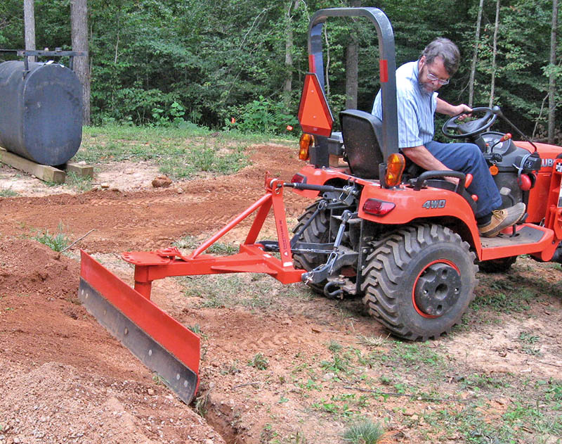
With the inspection complete, Louise and Michelle used hand tools to cover the cables with six inches of dirt so we could lay a yellow plastic "CAUTION" tape above them. Then Mike used the tractor to pull-in the remaining foot of dirt.
We were very fortunate that the rain didn't start in early morning, as predicted. It was 1:30 PM before the inspector arrived, and she stayed over an hour, but still we were able to fill the trench before light rain began at about 5:30.
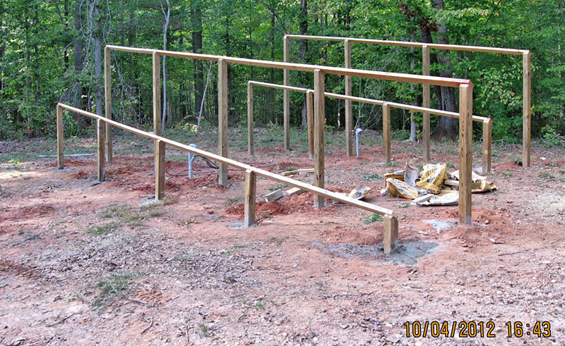
What have we been doing for the past 10 days? Well, for starters, we bought additional lumber needed for the PV supports. Then Mike made a plywood jig that we will use to set the spacing between rows of posts in their holes. Proper front-to-back spacing is vital for the PV panels to fit the bolts we installed in the 2x4 support rails.
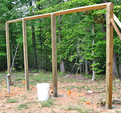
Next we cut the 2x4 support rails to length, drilled the holes, and inserted the PV mounting bolts. Yesterday we cut the top end of each 4x4 post to the 42° angle needed by the rail. Today we bored holes for the first two (longest) posts and set them, backfilling the holes with concrete around the posts.
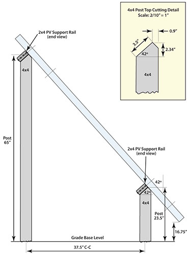
The drawing below shows the front and rear PV support posts, with the end-view of the 2x4 support rails angled 42° and bolted to the tops of the posts.
You might wonder about the "longest posts" mentioned above, since the drawing shows the rear post only 65" above the ground. In fact, this refers to the grade reference height, which is located at the corner diagonally opposite where we were working today. The ground level at today's corner post is 40" lower than that, leaving 8'-9" of post above ground. With two feet buried in the ground, this post is nearly 11' long! Thankfully, we'll be working with shorter posts as we progress toward the opposite corner.
 |
|
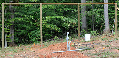
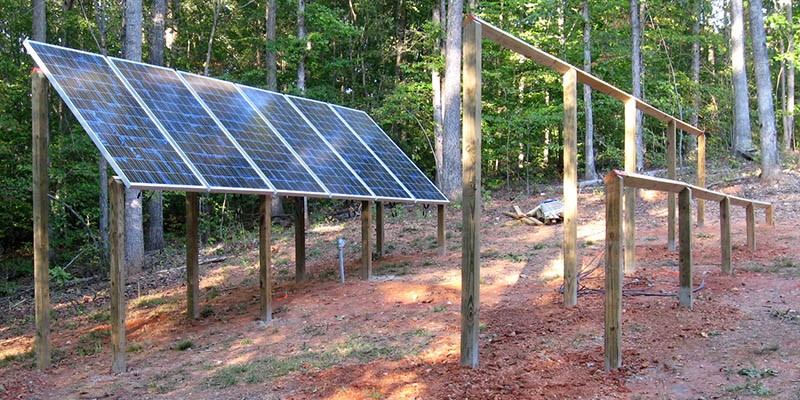
Today we bored holes for two more PV support posts and planted those posts. The slope of the ground is evident in the righthand photo. Fourteen more holes and posts to go.
|
 |
We used the power auger to bore four holes and set the four 4x4 posts for the front row of the north set of PV panel supports. Only 10 holes and posts remain for the south set of panels.
In the evening, Mike and Michelle alternately used an eight-pound sledge to drive an 8' steel ground rod into the earth.
This section of the supports is ready for six PV panels to be installed.
|
|
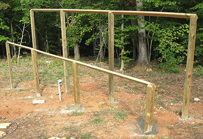
The left photo shows the complete north supports. On the right is a thin plywood spacing jig that has four holes to match the corner holes of two side-by-side PV panels. Once a pair of rear posts and their rail are in place and the front posts and rail are being positioned, the jig is placed so the holes fit over mounting bolts we inserted in both rails. With all four holes engaged, the rails are spaced correctly, and the front support posts can be given final adjustments for plumb, then fixed in place with concrete.
We set the first two posts and rail on the back row of the south set of PV panel supports, then it began to sprinkle, so we quit. Rain is forecast for the next two days, so it looks like we'll have some time off.
We set the remaining three posts and rails on the back row of the south PV panel supports. Only five posts remain, and they're all short, which makes the work much easier.
We bored holes for and set the five posts and four rails on the front row of the south PV panel supports. Tomorrow we plan to install the PV panels and the combiner box, and begin wiring them together.
We finished preparing the south supports by driving an eight-foot ground rod into the earth between the two rows of posts. Then we mounted six PV panels on the north supports, a significant milestone. Tomorrow we'll mount the remaining eight panels on the south supports.
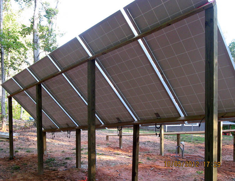
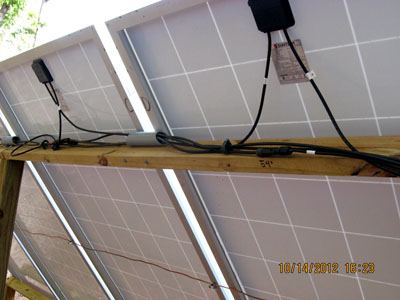
The rear view below shows how the panels rest on the horizontal rails between the posts. The panels are spaced 2" apart, and are secured by nuts and washers on carriage bolts inserted upward through the rails.
Note: Diagonal bracing between posts will be added after all PV panels are mounted.
We installed the remaining eight PV panels on the south supports. All panels are now mounted. We grounded their metal frames to protect against lightning. When the rain stops on Tuesday, we will bolt the combiner box to a support post and wire the panels to it, and also will connect the feed cables running to the house.
We mounted the combiner box on a rear support post under the south PV panels, extended the feed-cable conduit to it, and connected the four feed cables to terminals inside the box.
Today we ran cables to connect the seven pairs of PV panels to the combiner box (left). We also installed plastic pipe hangers to "dress" the cables where they run along the rails (right). The short lengths of gray PVC conduit shield the cables from direct sunlight. Even though the cables are supposed to be resistant to ultaviolet light, we chose to protect them as much as possible from UV deterioration.
|
|
All that remains on this project is to install diagonal bracing between the PV support posts and have an electrician connect the system to the house electrical system.
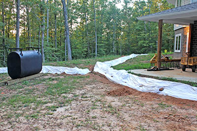
After the electrician came to look over the work that needs to be done to complete the system, Mike moved the diesel generator to its permanent location. He used forks that clamp onto the tractor bucket, and placed the generator on 4x4 timbers spiked-down with ½" rebar. Tomorrow the electrician will connect the cables from the solar equipment to the generator's output.

|
|
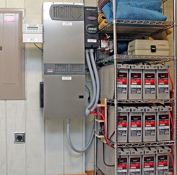
Two electricians arrived at 7:00am today to wire the solar power system into the home electrical system, and to connect the diesel generator. They finished in only 4½ hours, so everything is ready for the initial checkout and final county inspection. This photo shows the complete system without the rat's nest of cables that have been cluttering our equipment room for the past month-and-a-half.
A small amount of work remains to be done on the generator remote-start wiring, but this will have to wait until we receive a couple of parts next week.
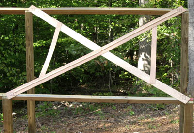
We installed most of the diagonal bracing needed on the solar panel supports. Three more braces (shown here leaning against end posts) remain to be attached after we buy more lag bolts.
After Louise bought six more lag bolts, Mike installed the remaining three braces on the PV supports. This structure is complete and ready to harvest solar energy.
Yesterday we commissioned the solar power system by following the steps in the owner manual and performing the initial configuration. Today we verified the configuration settings and switched the system to power a couple of loads in the house (two ceiling lights and the HVAC unit). The system worked perfectly, charging the batteries from the PV panels and powering the loads from those batteries when we switched-off the breaker feeding the grid to it.
All that remains is to finish wiring and testing the diesel generator, and getting the final county inspection.
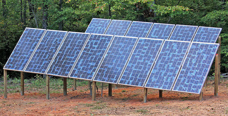
The county inspector stopped by and gave us a passing grade on the final inspection of the project. Now we can put the system into service. Here is a photo of the finished system.
Yesterday, after the inspection, we built a low wooden frame around the generator, plus a temporary shelter to keep off the rain. Today Mike filled the frame with gravel to eliminate mud splashing onto the generator.
We bought a plastic dog house to shelter the generator. It required some surgery to remove most of the floor (but still leave enough to hold the sides in place), and to cut holes in one side for electrical cables. Ultimately we will add aluminum louvered vents on the opposite end to provide additional ventilation.
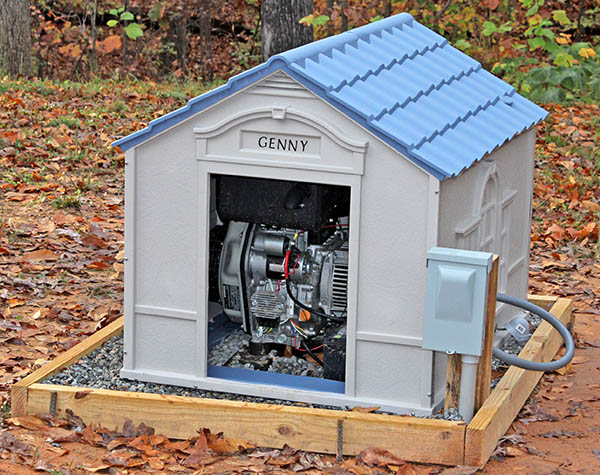
Mike added an awning over the door of the generator shelter to reduce the chance of rain blowing in. He also cut a hole in one side and installed a grille and a small fan that operates while the generator is running, and blows outside air toward the generator's cooling intake. Warm air exits the shelter via two gable vents and through the door.

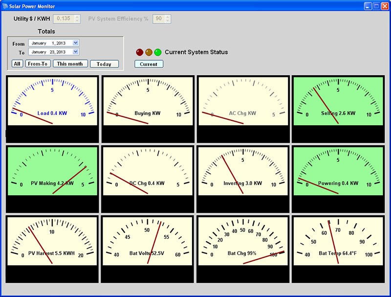
Mike wrote two programs to monitor the solar power system operation. One, running on our Linux server, receives data from the system and stores it in a database. The second program runs on a PC, retrieves data from the database, and displays "meters" showing various aspects of the system. This screen shows the solar panels producing 4.2 KW at 11:30 AM on a bright January day. The system is powering the 400-watt house load and selling 2.6 KW to the utility. The PV Making meter face turns green if the solar panels are harvesting energy. The Selling and Powering meter faces turn green when the sun is saving us money, and the Buying meter face turns red when the system is buying power.
Updated May 23, 2023