Project: Observatory – Installing the Telescope Mount
April 14, 2018 – Telescope mount installation
After 10 months of construction, the observatory is at last ready for the telescope mount! Mike began assembly today.
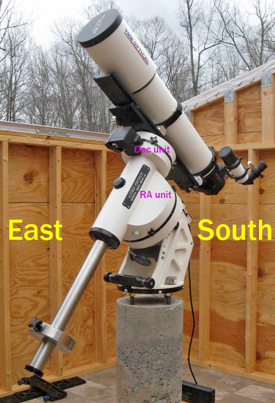
This seemingly minor task actually is quite involved. The computerized mount is large and heavy, and its components are packed in several cartons separate from the telescope. These photos illustrate the initial installation, which will be completed when the sky is clear enough for a polar alignment.
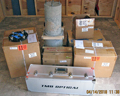
The mount components are in the cardboard cartons. The telescope itself is in the silver case.
|

Step 1: Bolt the base plate to four threaded rods embedded in the concrete pier. The plate must be as level as possible, so Mike adjusted leveling nuts under the base plate while watching a machinist's level where each graduation represents 0.005" elevation over 12".
|
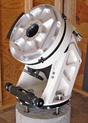
Step 2: Attach the 50-pound "RA" (Right Ascension) unit to the base plate. This unit tracks targets across the sky from east-to-west as the Earth rotates.
Four bolts with silver knobs (two visible in this photo) secure the RA unit to the black base plate, but these remain loose until a polar alignment is performed.
|
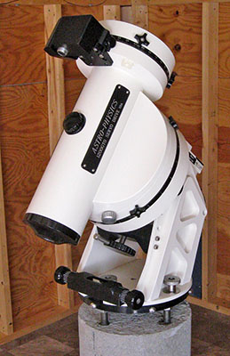
Step 3: Clamp the 31-pound "Dec" (Declination) unit to the large round plate on the RA unit. The Dec unit positions the telescope to the target's north-south position.
|

Step 4: Screw the 14-pound stainless steel counterweight shaft onto the Dec unit.
|

Fifty-six pounds of stainless steel counterweights. Ultimately, only two of the large 20-pound weights were needed to balance the telescope and imaging equipment
|
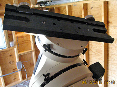
Step 5: Bolt a "dovetail plate" to the Dec unit to hold the telescope. The plate holds a dovetail "rail" on which equipment is mounted.
|
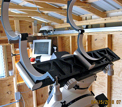
Step 6: Attach a dovetail rail to the dovetail plate on the Dec unit. The circular clamps on this rail hold the telescope.
|
Ta-da! – The telescope!
The final step is to clamp the telescope (the Optical Tube Assembly or "OTA") in retaining rings that are bolted to the dovetail rail clamped on the Dec unit. In this photo, the telescope has no eyepiece or camera attached. The right-angle eyepiece is attached to a small "finder scope" used to roughly align the main telescope to a desired target.
A 10-pound weight is secured to the counterweight shaft where it achieves balance in all positions of the scope.
April 21, 2018 – Polar alignment prep
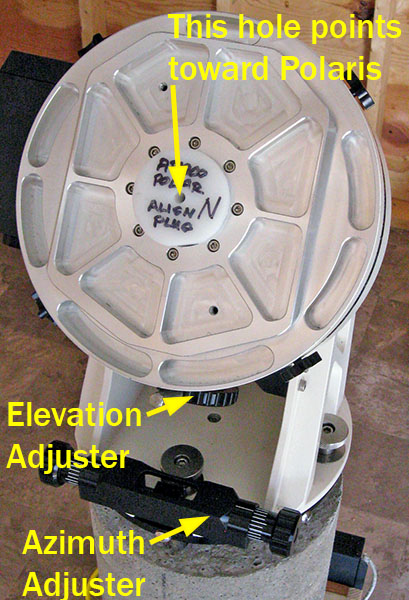
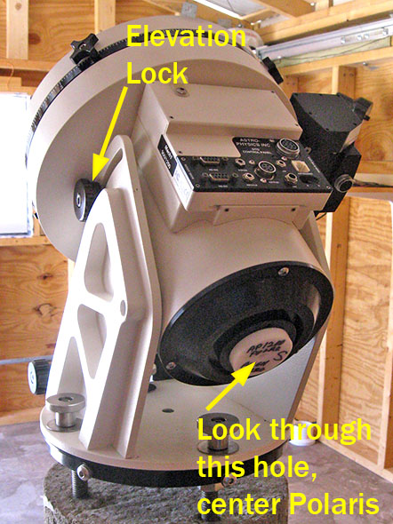
For accurate tracking of targets across the sky, the RA axis of the mount must be physically aligned with the Earth's axis. This involves adjusting the azimuth and elevation to center Polaris, the North Star, in a hole running through the RA axis.
The hole through the RA axis is 1½" in diameter, making it easy to spot Polaris, but difficult to achieve precise alignment. To improve accuracy, Mike machined two Delrin plugs with central 5/16" holes. The large plug fits into the north end of the hole, and the small one fits into the south end. The red plastic tape provides a snug fit in the threaded hole.
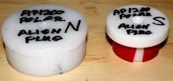
The two photos below illustrate how the adjustments are made, and how the plugs fit into the RA axis. Before fitting the plugs, Mike will look through the RA axis from the south end and adjust the azimuth and elevation to roughly center Polaris.
Then he will insert the plugs, and adjust the azimuth and elevation to center Polaris in the 5/16" holes. This should be simple because we aligned the bolts in the pier top fairly accurately north-south before the concrete set. Also, our new observatory is only 0.15° farther north than the former location, so the mount's old elevation setting will be very close.
With Polaris centered, Mike will tighten the azimuth locks on both sides, and tighten the four bolts that secure the RA unit to the pier plate.
Polar alignment might have to wait, because clouds are coming in, and the weather forecast calls for rain over the coming week.
April 24, 2018 – Interior decoration
Mike recently bought a "craft cutter" machine, and used it to create 2½" orientation labels for the observatory walls. The labels are cut from thin vinyl backed with a permanent adhesive.

April 29, 2018 – No polar alignment yet
After eight days of clouds, the sky finally cleared, and Mike used the opportunity to attempt a polar alignment of the RA unit. Alas, this was not to be. Now the moon is full, and its light made the sky so bright that Polaris could barely be seen.
Mike saw Polaris briefly, and adjusted the RA unit so the star appeared to be roughly centered in the large axis hole, but it was too faint to see through the 5/16" hole in the plugs he made.
April 30, 2018 – Sneaking up on a polar alignment
The moon rises about one hour later each successive night, so the northern sky was darker tonight. Mike tried to spot Polaris, and had some success – it was easier to see the star, and it seemed to be visible a couple of times through the hole in one of the plugs. Mike tweaked the RA unit's alignment until Polaris appeared centered. Maybe tomorrow night will be dark enough for a good alignment.
May 1, 2018 – Polar alignment, step 1 done
The sky definitely was darker tonight at 9 PM than it was the two previous nights, and Mike tried again for a polar alignment. He might have succeeded. Polaris flashed briefly through the plug holes several times, and the star appeared centered in the large hole through the RA axis without the plugs.
May 3, 2018 – Polar alignment, step 2 prep
Mike attached the mount's Dec unit to the RA unit, then mounted the telescope on the Dec unit. He planned to perform the next polar alignment step, but clouds rolled in, and no stars were visible.
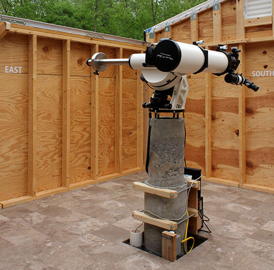
This photo shows the mount and scope in the "Park 1" position, where the telescope tube is level and pointing north, and the counterweight shaft is horizontal and pointing east. Using a machinist's level, Mike loosened the clutches and adjusted the mount until both were dead-level.
When the sky clears Mike will continue the alignment process.
May 8, 2018 – First light
"First light" occurs when a new telescope first passes starlight to an observer's eye. That occurred tonight, under a very dark and clear sky.
Mike confirmed that the mount still operates correctly – slewing the telescope at a reasonable speed, and not crashing it into the pier. He also connected the control box for the electric focuser, and brought stars to focus in an eyepiece.
Tonight's goal was to perform a "drift alignment" to refine the initial polar alignment originally set by centering Polaris through the RA axis.
The procedure involves pointing the telescope to a star low in the south, then checking in a crosshair eyepiece to see how quickly, and in which direction, the star drifts away from center.
Depending on the star's drift direction, the mount's azimuth is adjusted slightly east or west, and the drift is monitored again. Negligible drift over 10 or 15 minutes means the azimuth is correctly aligned.
This procedure is repeated with a star low in the east, and adjusting the mount's elevation until there is negligible drift over 10 or 15 minutes.
Things didn't go as hoped because Mike made a mistake pressing keys on the mount's keypad. He will try again tomorrow night.
May 9, 2018 – Drift alignment complete
Mike repeated the drift alignment with good results, and declared the mount to be polar-aligned.
June 14, 2018 – First telescope image
After weeks of clouds and rain, the sky finally cleared enough for Mike to perform some initial tests.

This image of Jupiter isn't very good, but it proves the telescope, camera, and software all work.
It leaves much to be desired because the atmosphere was unstable. In such conditions, the air randomly refracts light rays, so the real-time image "squirms" or "boils." It's impossible to capture a sharp image, even with very short exposures.
One way to deal with this is to make a "movie" of short-exposure frames, and run it through special "stacking" software that evaluates each frame and combines the best frames to produce a single image. This image is the result of 180 frames – it's better than a single frame, but would be much better if made in stable air.
|

Here you can see how bad the conditions were. This star should be a round white pinpoint, but it flared to one side during the 50-millisecond exposure. We can only hope for more stable atmosphere in the future.
|
June 17, 2018 – Telescope parked
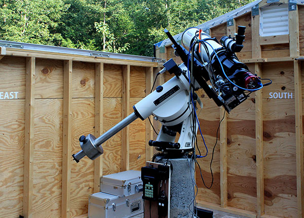
This photo shows the telescope in its custom parked position, pointing southeast.
Even though the equipment is taller than the Park 1 position. it's low enough to easily clear the closed roof. It also provides more walking space around the scope than Park 1, where the scope and counterweight shaft projects horizontally from the mount, consuming the maxium space.
June 18, 2018 – Moon image
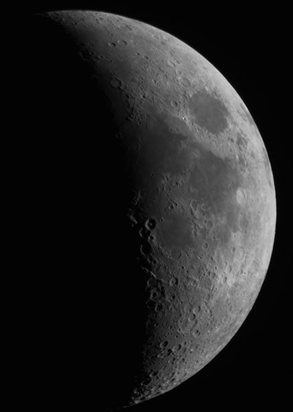
The sky cleared briefly tonight, and Mike photographed the waxing moon. The stacking software processed 2,000 frames, each exposed for 6 milliseconds, to produce this single image.
Note: The astro images on this page illustrate progress in setting up and testing the observatory equipment. When the telescope is fully operational, Mike will post new images on our
astronomy website instead.
June 24, 2018 – Another Moon image
Mike used clear but humid skies to calibrate the telescope mount's sky model, and then shoot another Moon image. "Calibrating" the mount means commanding it to slew to a particular star, then manually centering that star on the camera's sensor, and finally commanding the mount to adjust its sky model accordingly. Now future slews to objects will be very accurate.
This image of the nearly full Moon consists of 200 frames from a stack of 2,000, each exposed for 2 milliseconds.

July 7, 2018 – First deep-space image
The human eye is not sensitive enough to detect color in most faint seep-space (vs. solar system) objects, but modern astronomy cameras and software team-up to help with "electronically-assisted astronomy," or EAA. EAA displays on a computer screen a "stack" of 5-10 (or more) individual images. The resulting image clearly displays the target object in bright full color that the eye simply can't see.
Here is the EAA image Mike captured tonight. It is a stack of seven 20-second exposures, slightly tweaked in Photoshop for a darker background and brighter nebula. the nebula is small; this is the camera's full frame. There is plenty of sensor area for larger objects.
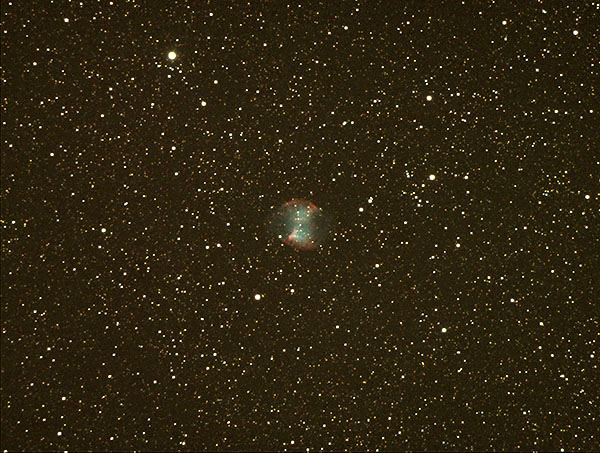
This cloud of gas, called a "planetary nebula," is known as the Dumbbell Nebula, or Messier 27, and is about 1,360 light-years from Earth. Even though it appears small to us, M27 is estimated to be about 2.9 light-years in diameter (17.4 trillion miles).
Note: This image would look better with additional processing to darken the background and reduce the "noise" (graininess). But Mike wanted to show what an EAA image looks like as displayed at the time.
July 27, 2018 – New astronomy camera
This is the new camera Mike bought for the telescope. The black device attached to the red camera is a motorized filter wheel that holds up to five optical filters. Currently it has an infrared-blocking filter, two narrowband filters, and an opaque plug to cover the camera sensor while exposing "dark frames" that are applied to images to reduce electrical noise (speckles).

Telescope guider
This is the camera and small scope Mike uses to "guide" the telescope. Software on the observatory computer monitors the position of a star on this camera's sensor, and sends correction commands to the mount if the star drifts.

A guided telescope tracks the target with arcsecond accuracy, enabling the main camera to produce sharp images. Without guiding, stars can become elongated, the target blurred, and details lost.
Precise guiding is necessary for long exposures, and Mike's goal is to make many such exposures of an object, each for five minutes or more, then stack them into a finished photograph.
August, 2018 – More setup and a webcam
Telescope setup is almost complete. Now the planetarium software can connect to the main camera, its cooler and filter wheel, the motorized focuser, and the guide camera. All that remains is to "calibrate" the guider so it issues accurate corrections to the telescope mount, and test the focuser. Both require clear skies, which are not forecast for at least a week.
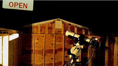
Mike bought a webcam so he can view the observatory interior remotely to ensure the roof is open and the telesope hasn't somehow gotten into a dangerous position. He also installed LED lights to illuminate the scope (these can be switched on remotely).
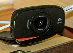
He attached plywood signs lettered "Open" and "Closed" to roof trusses at each end, and visible in the webcam's upper-left corner. If the "Open" sign isn't there, don't move the telescope!
You might wonder why the "Closed" sign is even necessary, since the roof trusses are clearly visible. The answer is, the sign indicates the roof is fully closed. This is hard to tell just by looking at the trusses. Likewise, the "Open" sign indicates the roof is fully open.
Updated
May 23, 2023


