|
|
|
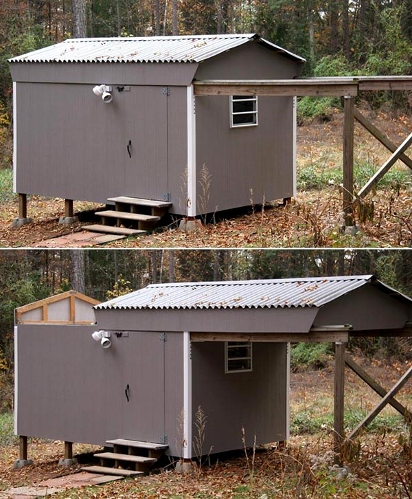
Louise and I became interested in amateur astronomy in 2000, and in spring 2001, we built an 8' x 12' observatory with a roll-off roof (photos) that served us well until we moved to a new house in January 2011.
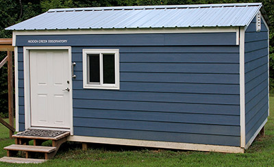
After six years devoted to other projects, we began building this 10' x 14' observatory in June 2017, and completed construction 10 months later in April 2018. We named it Hidden Creek Observatory because it can't be seen from Creek Road, where we live.
Setting up and testing the equipment consumed four months, and the observatory became operational in August 2018. But resolving a problem with the imaging camera delayed full operation seven more months, until March 2019.
Click here to see how Louise and I built this observatory over 10 months.
Opens in a new browser window. Close it to return here.
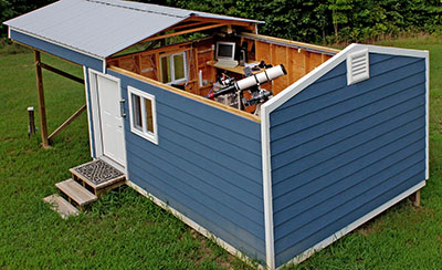
A screw-drive garage door opener opens and closes the roof, which rides on 10 three-inch hard-rubber wheels rolling on 2x4 pressure-treated wood tracks attached to the top of the east and west walls. These tracks extend 11 feet beyond the north wall to 4x4 support posts.
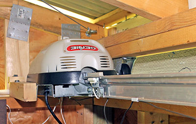
Installing the opener upside-down with the motor and track facing upward allowed a simple attachment to the roof. The motor is bolted to the northeast corner walls, and the track's end is bolted in the southeast corner. The trolley arm is attached to a nearby roof truss.
|
|
This view shows the motor in the background and the track along the east wall. The center of the track is screwed to an angled 2x4 so it doesn't sag, and also to prevent it from lifting as the trolley passes.
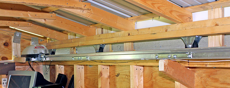
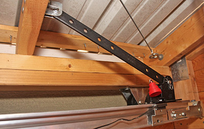
Corner-to-corner 1/8" steel cables with turnbuckles transfer some of the opener's force from the east side to the west side, and prevent the roof from skewing while moving.
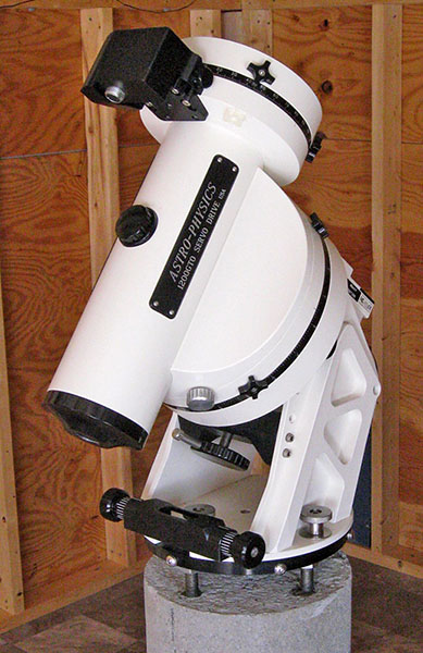
A 12"-diameter concrete pier reduces to 10" at the top, and is isolated from the floor to minimize vibration transmitted to the telescope. A TMB-130SS telescope is mounted on an Astro-Physics 1200 mount, which is attached to steel rods embedded in the pier.
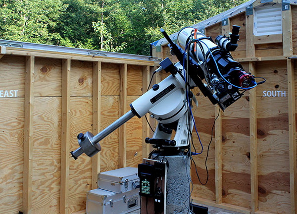
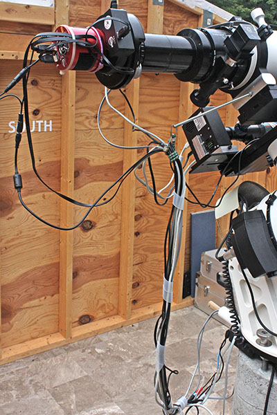
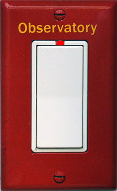
Direction labels on the observatory walls orient visitors unaccustomed to observing the night sky. The 2½" letters were cut from self-adhesive sheet vinyl with a craft cutting machine.
The mount is attached to an Astro-Physics SPA 10" Standard Pier Adapter that is bolted to four ⅝" threaded rods embeded in the pier. When we cast the pier, I bolted these rods to the SPA, inserted them into the wet concrete, then blocked the SPA level until the concrete cured.
I drilled and tapped a ¼"-20 hole in the top end of each rod, and cap screws hold the SPA to the rods, with leveling nuts underneath. I adjusted these nuts until the SPA was level to within 21 arc-seconds on a machinist's bubble level, then tightened the cap screws.
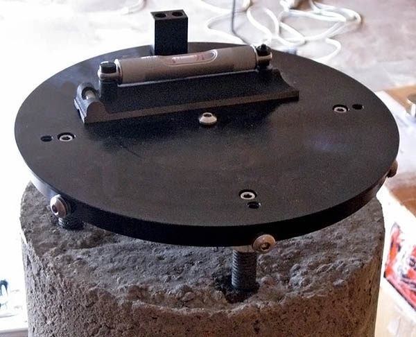
Four bolts with silver-color knurled knobs (two visible below) attach the AP1200 base to the SPA. The black device in the foreground pivots the base to adjust the azimuth during a polar alignment, then the four silver knobs are tightened.
The telescope mount and imaging equipment use several power supplies and other devices. I needed a way to keep these and an Ethernet power switch off the floor, and to manage their cables.
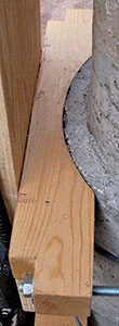
I made four brackets by sawing 6"-radius arcs in lengths of 2x4 lumber, then used 5/16" threaded rod to clamp pairs of these brackets to the 12" pier. Plywood panels screwed to the brackets hold the equipment.
The south panel holds the Ethernet power switch I use to control power to telescope equipment from my home office. Above-left of that is a 15-volt switching power supply for the AP1200 mount. To the right of the power supply is the remote box of a four-port USB 3 extender that connects the two cameras, rotator, and focuser to the computer.
The yellow power cord from the Ethernet power switch is plugged into a receptacle fed through conduit under the floor. The back of the north panel (below) is barely visible in this photo.
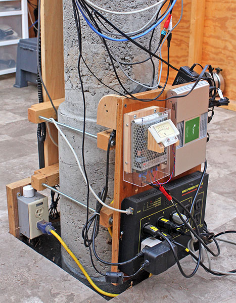
I bent clear plastic to form a cover for the mount's power supply. It extends over the electrical connections at the bottom, and leaves space around the metal case for ventilation. Anderson Powerpole connectors, widely used by amateur radio operators, connect the mount's power cable to the DC output terminals.
The north panel has a hook for the AP1200 mount's remote keypad, top-left, but it's usually in storage because a computer controls the mount. On the right side of this panel are the motorized focuser's hand control, connection hub, and power supply. The gray electrical box seen in the photo above is screwed to the short 2x4 in the corner of the pier hole.
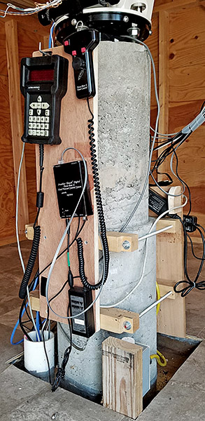
The pier enters the observatory through a 16"x18" hole in the floor to isolate it and minimize vibration. Plastic window screening keeps out rodents, snakes, and other curious animals (but not bugs, which come in around the roll-off roof). The screen also catches small parts that drop while working on equipment at the pier. Construction adhesive secures it to the pier and the floor framing.
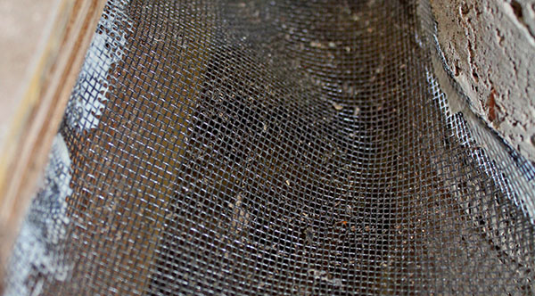
Mice and some other critters climb the 4x4 wood posts supporting the roll-off roof tracks, then walk those tracks into the observatory. To prevent this, I glued a band of window screening around the top of each post.

I built motorized lens caps to avoid walking out to the observatory to remove the telescopes' caps at night and put them back in the morning. Here's a video of the lens caps in action. Opens in a new browser window. Close it when done.
Both lens caps are 3D-printed from plastic. They are only 1/10-inch thick, but lightweight and rigid enough to close snugly against the telescope dew shields.
Each lens cap is attached with a 3D-printed bracket to a servo motor controlled by an Arduino microcontroller. A program on my computer sends "open" and "close" commands to the Arduino via Ethernet.
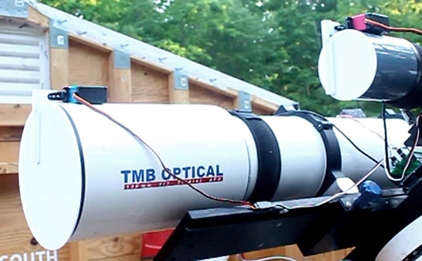
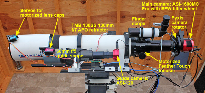
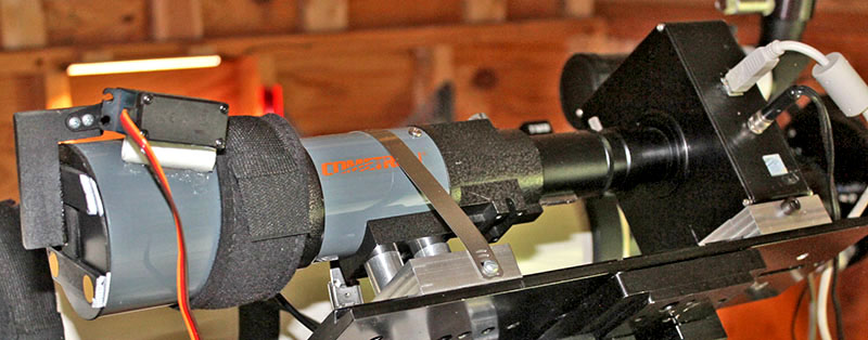
This photo and the closeup below it show the telescope and imaging equipment. A ZWO ASI-1600MC Pro CMOS color camera with an EFW filter wheel is attached to an Optec Pyxis rotator that connects to a Feather Touch motorized focuser on the TMB130SS telescope.
The telescope is clamped in rings bolted to a dovetail plate. Another dovetail plate holds the guide scope and its camera alongside (see below).
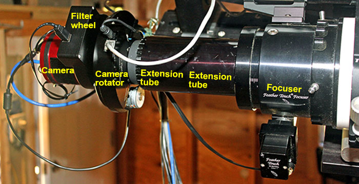
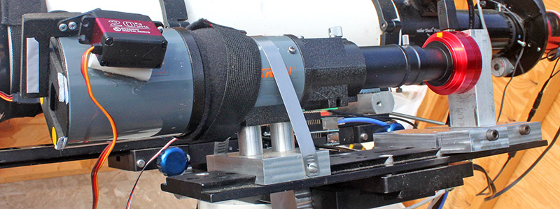
Here is a closeup of the imaging equipment.
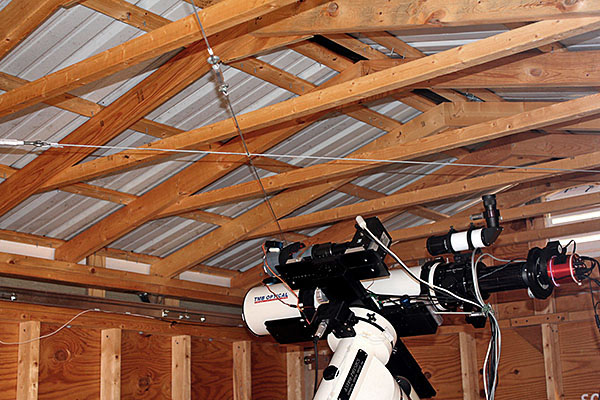
No one is present in the observatory while the telescope is acquiring images, so it is imperative that the telescope be able to point anywhere in the sky without snagging the cables to the imaging equipment.
The cables are bundled together with short sections of plastic spiral wrap, and a mini bungee cord secures the bundle to a ¼" threaded rod screwed into an aluminum block under the telescope. As the telescope moves, the rod holds the cables away from the equipment on the south side of the pier.
The red camera must rotate 180° in both directions, so its two cables loop to the bundle.
It is necessary to "guide" the telescope for pinpoint sharpness (details here). Software controlling a camera attached to a second scope locks onto a guide star and issues corrections to the mount to achieve precise tracking, resulting in sharp images on the main camera.
An inexpensive 60mm f/5 telescope and an SBIG ST-402 camera (replaced in 2021; see below. below) are mounted on a dovetail plate alongside the main scope. The black strap wrapped around the scope is an electric heater that prevents dew from forming on the lens. The servo motor that opens and closes the lens cap is just to the left of the heater strap.
In June 2021, the ST-402 camera stopped working, so I replaced it with a new ZWO ASI-120 monochrome camera.
Astronomy camera prices have plummeted over the years! The new ASI-120 cost $179 – just 16% of the $1,100 paid in 2005 for the second-hand ST-402.
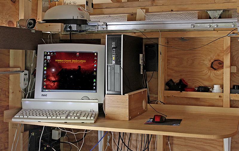
A homemade desktop is attached to the northeast corner walls to hold the computer and monitor. The desk is 44" high to allow comfortable operation while standing. The corner is rounded to make it "dark-friently."
Yes, that's an old heavy CRT monitor. It works well, even in sub-freezing temperatures, unlike LCD monitors.
Above the monitor is the garage door opener that rolls the roof open and closed.
On the wall beneath the desk is an Ethernet power switch I control from my home office to switch power to computer equipment and the roof opener.
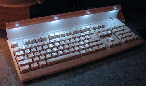
Four white LEDs glued to a piece of styrene behind the keyboard make it easy to see the keys in the dark. Their ends are filed flat to diffuse the light, and they're wired to the keyboard's +5V power through current-limiting resistors and a toggle switch (far right).
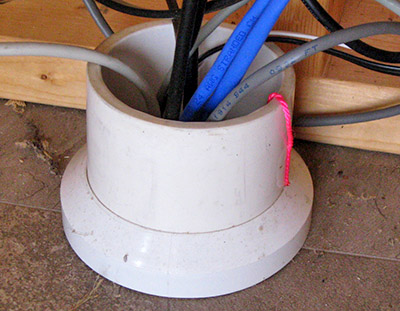
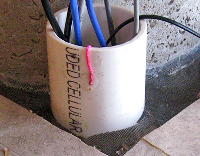
This 3" PVC pipe carries cables under the floor from the computer desk to the telescope pier. The red string, each end glued to the conduit, has a loop in the middle to pull additional cables. The excess string is dropped into the conduit, and stored there until needed.
|
|
I built a heater to pre-warm the computer on very cold nights. It consists of a 60-watt terrarium heater (not an aquarium heater) and a thermostat in a wooden box beneath the computer.
Before an imaging session on a cold night, I turn on the heater. The thermostat is set to turn it off when the temperature in the box reaches 50°F. Eventually the heat migrates into the computer case.
|
The computer rests on its side atop the heater box. 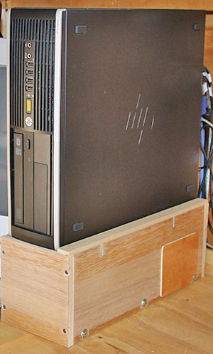
|
Two aluminum rails set in slots cut into the box sides support the computer. A thermostat is installed in a metal electrical box glued to the bottom of the box. An AC power cord runs through a 1" hole in the rear panel. 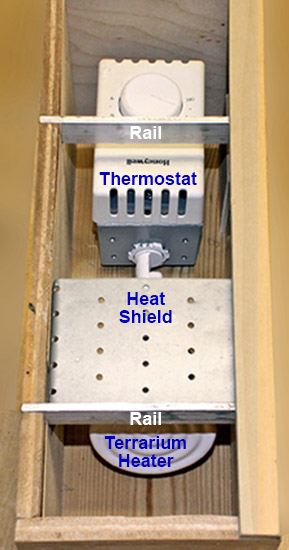
The terrarium heater screws into a socket on one end of the electrical box. A metal shield above the heater prevents a hot spot beneath the computer. |
The thermostat is a Honeywell model CT410A, intended for electric resistance heating, and is available at home-improvement stores. It switches both sides of the AC line – a safety feature. 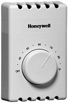
Do not use a regular wall thermostat intended for gas or oil furnaces, or heat pumps. Those are designed for non-lethal, low-voltage circuits. Aside from ruining the thermostat, placing household voltage on such a thermostat's unprotected electrical contacts could electrocute you. |
The observatory is 300 feet from our house and connected to the home network through a buried Ethernet cable. I use Windows Remote Desktop to operate the computer from my home office.
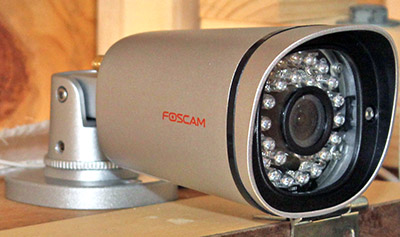
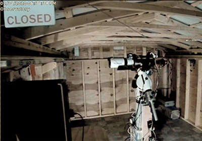
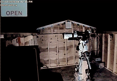
An Ethernet-connected security camera inside the observatory lets me confirm the roof is open, the lens caps are open, and the telesope is moving properly before I begin an imaging session. I also check it the following morning to be sure the automation software has parked the scope and closed the roof.
Thin plywood signs lettered CLOSED and OPEN hang from roof trusses at each end, and are visible in the camera's upper-left corner. If the OPEN sign isn't there, I don't move the telescope!
|
|
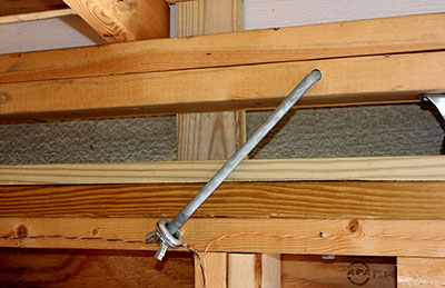
If high winds are forecast, I walk out to the observatory and lock the closed roof to the observatory walls with two J-bolts, one on each side (left photo).
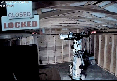
But I need to be sure the roof is unlocked and free to roll before attempting to open it remotely! The camera can't see the J-bolts, so after locking the roof I attach (with Velcro) a LOCKED sign to the CLOSED sign.
|
|
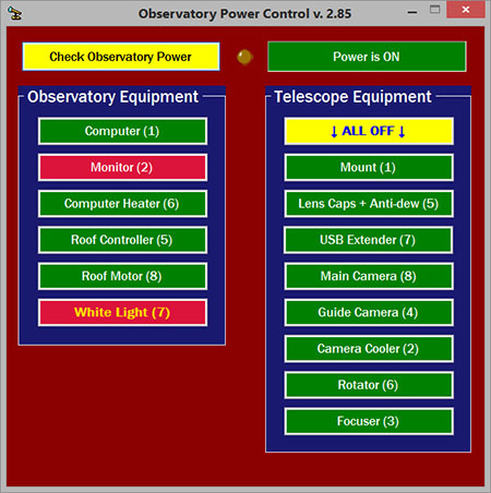
Fully remote operation requires a way to switch AC power to all observatory equipment from inside the house. I use two DLI Ethernet power switches, one under the computer desk and the second on the telescope pier. Each controller has eight outlets switched on and off via a Web browser page or with commands sent by a utility program supplied by DLI.
I wrote a program that uses the DLI utility program to switch the outlets and receive their current states. Here is a screen shot.
|
|
The wall switch shown on the right is located in our workshop, and controls power to the observatory. A control box in my office can operate this switch via X-10 power-line technology. This works well except when our solar power system intereferes with the X-10 signals. So I must walk downstairs and press the switch to power-up the observatory on a sunny day.
Most PCs have a Setup option to start-up automatically when power is applied (e.g., remotely), so there's no need to press the power button.
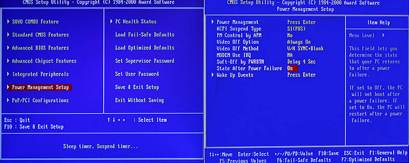
To activate this feature, turn on the PC and enter Setup by pressing the key displayed on the screen, typically F2 or Delete. Find and select an item labeled Power Management Setup or similar, then find an item labeled something like State After Power Failure, and select On. This means the computer will turn on when power is restored.
The photo below shows a Setup screen with these options highlighted in red. Notice the explanation on the right. This screen is from an old computer. Newer setup screens will be different, but should contain similar items.
Save the settings and exit Setup, then let the computer start up. Shut down normally, then unplug the power cord from the wall socket. Wait 15-30 seconds, then plug it in again. The computer should start. That's all there is to it.
OK, you can turn on the observatory computer remotely, but how do you shut it down? When using Windows Remote Desktop, the Start menu doesn't have a Shutdown option.
You need a simple command file and a desktop shortcut.
Open Notepad and type this into a new document: shutdown.exe /s /t 00 followed by a newline (the Enter key). Save the file with the name shutdown.cmd to your desktop or a folder on your hard drive.
Create a shortcut on your desktop for easy access to the saved file. I set the icon on mine to an X in a red circle for easy spotting.
Click here if you want to use this icon on your own PC. When the image opens, right-click it, then click "save to disk" on the popup menu. Opens in a new browser window. Close it to return here.
Note: After shutting down the computer in normal operation, be sure to kill the AC power to it so it will start automatically the next time you turn on the power.
One step beyond remote operation is fully automated imaging, where sophisticated software performs all the operations necessary to capture multiple subframes of one or more targets – all without my attention or intervention.
I use ACP (Astronomer's Control Panel) to do the job. ACP executes instructions in simple text-file "observing plans" that specify when to begin, which targets to image, how many subframes to collect on each target, and what to do at the end of the run.
ACP works with MaxIm DL to acquire images, and with FocusMax to focus the telescope.
This is a screen shot of the observatory computer with ACP acquiring images. FocusMax is in the upper-left, with ACP to its right. MaxIm at the lower-left displays a camera subframe of the Horsehead Nebula and Flame Nebula.
The MaxIm camera control window at the lower-right shows 578 seconds have elapsed of another 900-second exposure. Partially covering ACP is MaxIm's autoguider tracking error graph showing an average error of about ½ arcsecond.
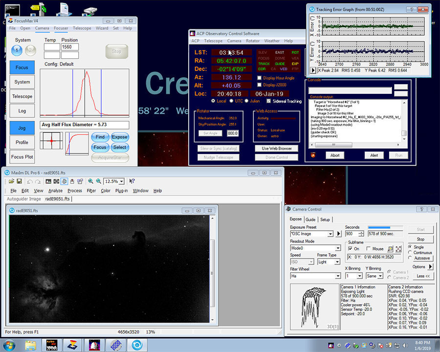
Normally I wouldn't see this, since ACP handles everything, and I don't need to be at the computer after starting the imaging plan.
For a night's run, I turn on the PC, power-up the telescope and imaging equipment, and launch ACP at any time – even before dark. I connect ACP to the telescope, roof opener, camera, focuser, and camera rotator.
ACP unparks the telescope and opens the observatory roof. I select the imaging plan, and ACP performs these operations:
In the morning, remotely from my office, I close ACP and the other programs, power-off the mount and the imaging equipment, shut down the PC, and kill the observatory power. Then I use PixInsight on my office PC to process the night's images.
Updated September 29, 2025