This project is complete! Scroll down to see day-by-day progress, or click the finished shed button above to see photos of the finished shed.
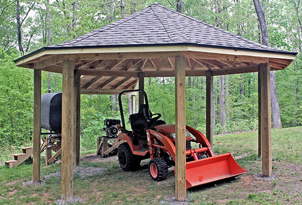
We are building a shed to store our Kubota BX-2360 subcompact tractor and implements.
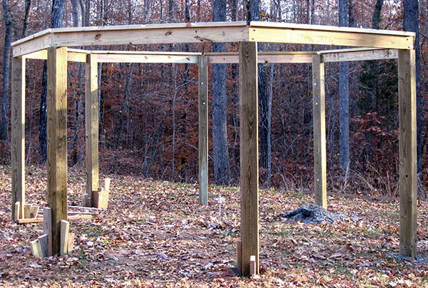
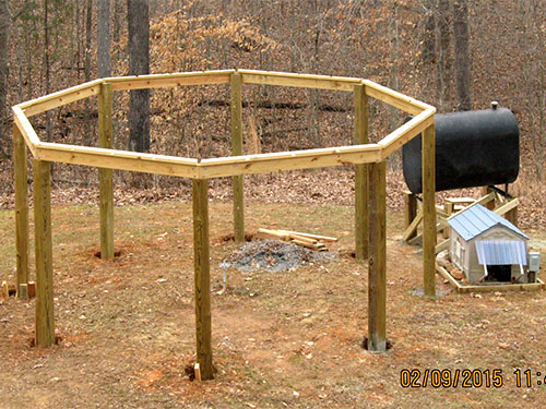
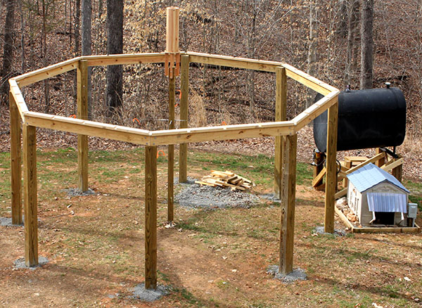
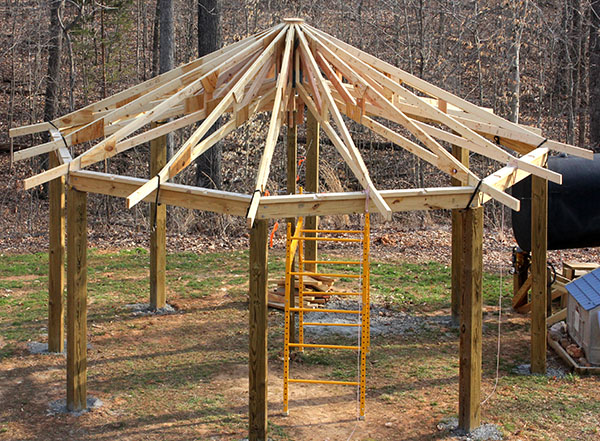
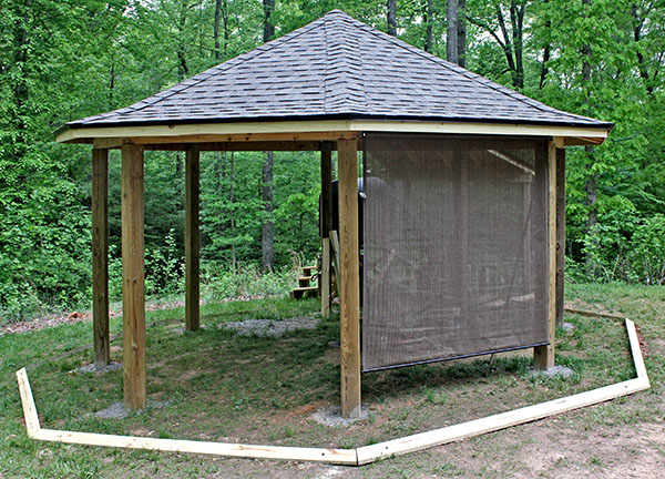
The shed is an octagon measuring 16¾ feet in "diameter" (apex-to-apex) that resembles our 18-sided (round) house. There are eight 6x6 corner posts with a 2x6 beam around the top to hold a dual-pitch (6:12 above 3:12) self-supporting truss roof (no center post) similar to the roof on the house. You can learn more about the roof below.

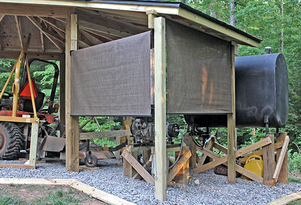
Each side is about 6½ feet wide, with nearly 71" clearance between the posts. Seven sides will be open, with pull-down exterior shades to shelter the implements from the elements. The eighth side will have solid siding because access is blocked by a generator for backup household power, and a 275-gallon tank holding diesel fuel for the generator and the tractor.
This drawing shows how we store the tractor and implements in the shed. The dashed line represents the 17" roof overhang.
Implements will be stored in seven bays, and the tractor will occupy the eighth. Implements in the six open bays will be stored with the three-point hitch facing outward, so the tractor can pick up and drop them from outside the shed. The finishing mower will be stored in the closed bay directly behind the tractor.
The landscape rake's tines and the rear blade must be rotated 45°, as shown by the green lines, so they will fit through the bay opening, and clear other implements. The gray positions won't work.
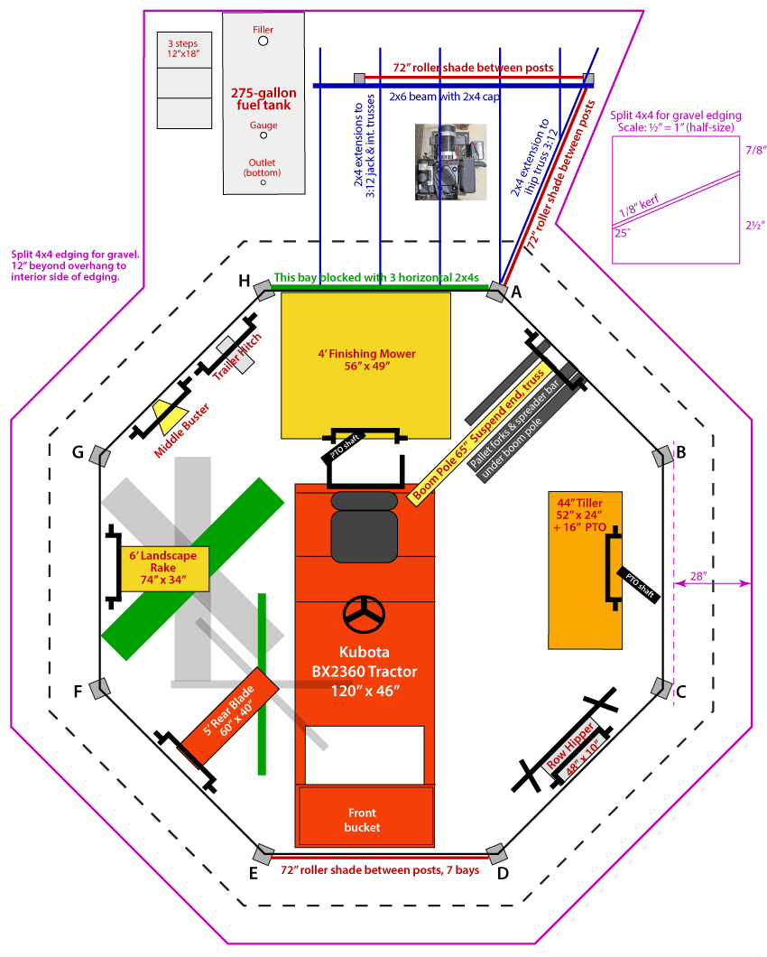
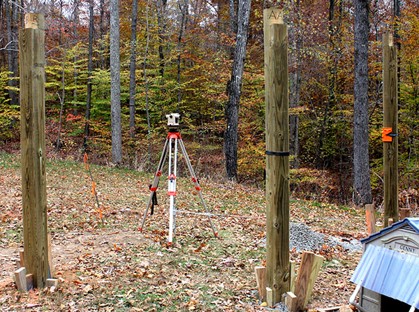
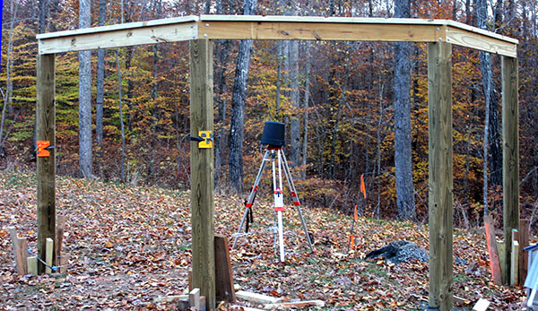
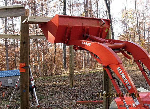
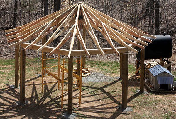
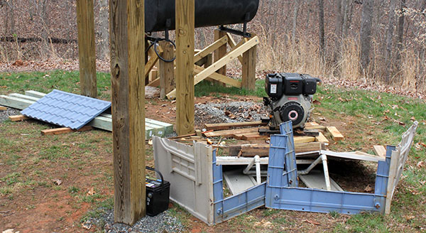
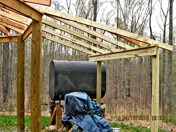
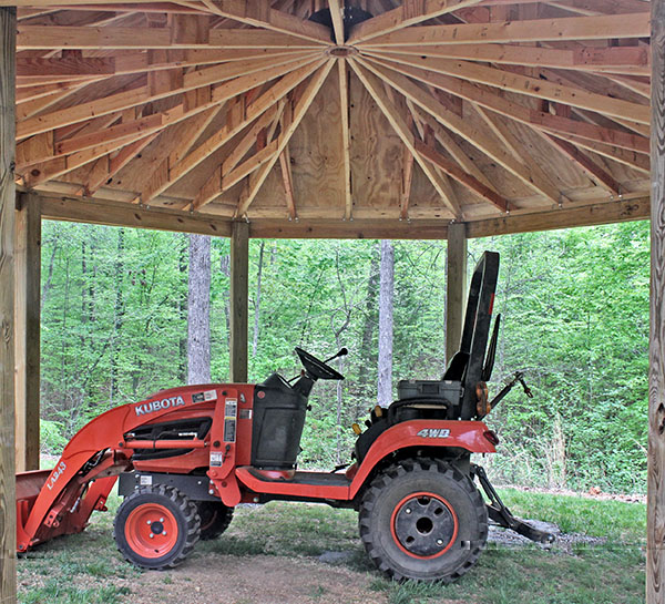
The drawing and this photo dramatically illustrate a major benefit of the self-supporting roof – the 10' tractor can be parked in the center of the 16' shed, impossible if there were a center post.
Another benefit comes from the octagonal shape, which encloses 196 square feet. A rectangular shed to store the same equipment would have four 6' bays on each side, making it 25' long. It would need to be 11' deep to accommodate the tractor, so the enclosed area would be 275 square feet – 40% larger.
The pink line encloses a 2½" gravel floor extending 12" beyond the roof drip line. The gravel will be enclosed by wood edging made by ripping 4x4s at a 25° angle. The angle provides a short ramp for the tractor to drive onto the gravel. The edging will be "nailed" in place with 2' lengths of rebar driven into the ground.
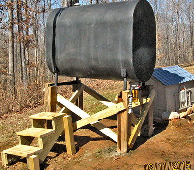
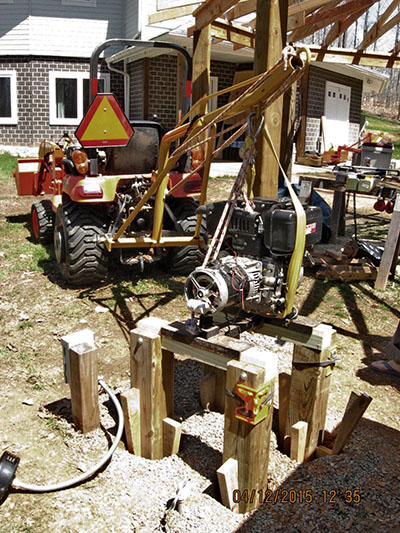
A 6 KW diesel generator and a 275-gallon diesel fuel tank will be outside the closed bay. The generator will be mounted to a platform 20" high. The fuel tank will be raised on 6x6 posts high enough to gravity-feed both the generator and the tractor fuel filler. Three steps will allow access to the tank's top fittings.
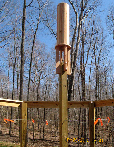
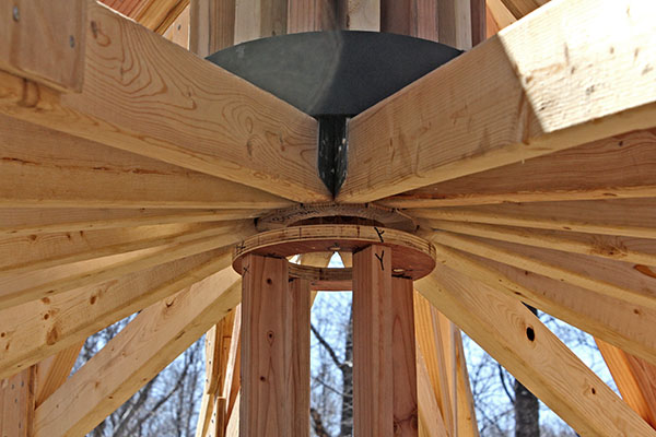
The octagonal roof will have 16 trusses that bear against a center cylinder, and will be clamped in place with a heavy steel split ring at the bottom. This clamp will be held together with ½" bolts, and it is this clamping force that holds up the roof. (There also are 16 shorter "jack" trusses that reach from the perimeter to the center of the main trusses, but do not bear against the cylinder.)
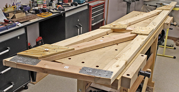
Several days ago we planed and ripped 30" lengths of 2x4 lumber into 16 pieces for the center cylinder. Each 30" piece has its edges beveled 11¼°. Sixteen such pieces form the complete 7½" diameter cylinder.
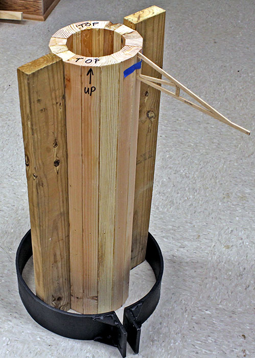
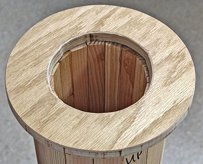
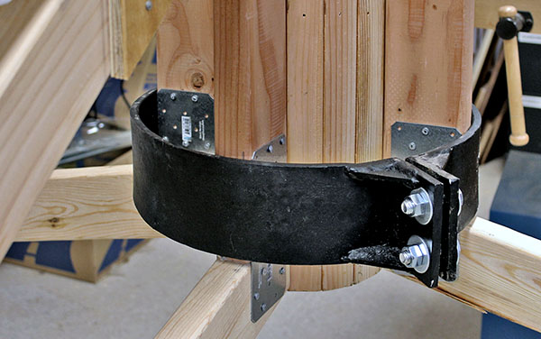
We glued the 16 pieces, clamping them with four large hose clamps until the glue cured. Here is the finished cylinder. Taped at the top is a 1:12 scale model of a truss, illustrating how these will butt against the cylinder. The 16 vertical truss chords, simulated by the two 2x4s, will be clamped to the cylinder by the black split ring that a blacksmith friend made for us.
As with our house roof, the hole in the center of the shed roof will be covered by shingles to keep out rain.
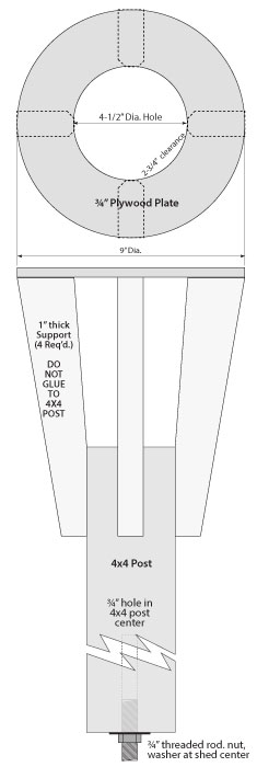
We will need a post to support the center cylinder and trusses as the trusses are placed in position. This drawing shows how we'll make this installation jig.
A 4x4 post with a ¾" hole in the bottom will rest on a nut threaded onto a ¾" center benchmark. The 4x4 will have four supports at the top that attach to a ¾" plywood ring. The cylinder will rest on top of this ring, and trusses will be placed around it, supported by the ring extending around the cylinder. Each truss will be "tacked" to the cylinder with nails through pre-drilled holes, to prevent it from tipping or sliding. The nails will be driven with a palm nailer by reaching up into the cylinder. This is the reason for the hole in the plywood ring.
When all 16 trusses are in place, they will be permanently clamped with the metal split ring shown above. The installation jig will be removed after the roof is sheathed by screwing-down the nut on the center benchmark rod.
We received approval from the subdivision archetectural control committee to build the tractor shed.
Mike spent a lot of time working in Adobe Illustrator to finalize the roof truss design, and calculate accurate measurements. Ideally we will be able to cut the truss components from the plan dimensions, and everything will fit perfectly.
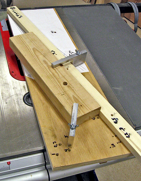
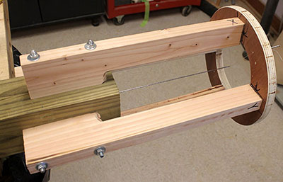
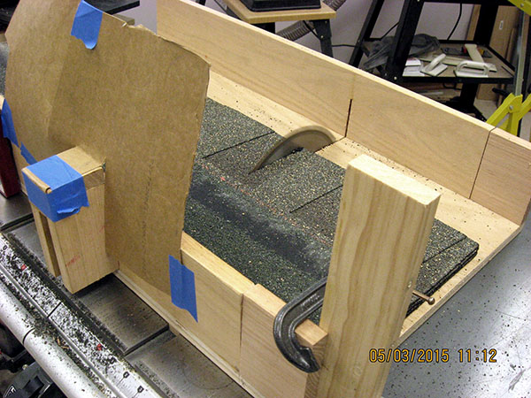
Some of the truss components require cutting a very shallow and precise angle, such as 12.6°. Mike made a template with lines at each of the seven angles. He then made a cutting jig for the table saw, and glued the template to it.
We will align the jig's adjustable fence to a template line, then screw it to the plywood base. The 2x4 beam rests on the base against the fence. Mike machined two aluminum clamps that secure the 2x4 to the base so it doesn't shift. All the screw holes for the fence, and bolt holes for the clamps are pre-drilled and labeled, so there is no question about what goes where for each angle.
The fence and the clamp bolts just be repositioned for each angle, but there are only seven angles, so this won't be difficult. Once positioned, we'll be able to make all the cuts for one truss chord, then set up for the next piece.
In this photo, a short 2x4 stands-in for the actual beam, which will be up to 9' long. The end will extend about an inch past the far end of the fence. The opposite end will be supported on a roller stand, and a second person will help feed it smoothly. The entire jig slides across the saw table, guided by an oak strip on the bottom that fits in the saw's miter gauge slot.
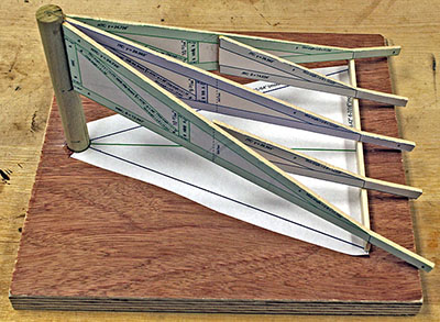
We are compiling a materials list, and need to know how many sheets of plywood will be needed to sheathe the roof. It is difficult to calculate the area of the sloping triangles, so Mike made a model that we can measure. He printed 1:12 drawings of the hip and intermediate trusses, then glued these on 1/8" wood. He used the band saw to cut around the truss outlines, then glued the trusses to a center column and scale 2x6 on a plywood base.
Note: In the actual tractor shed, the center column will end at the bottom of the trusses; it will not reach the ground. The trusses will be clamped to the column at the bottom, as shown above.
Next we will measure the roof area, and also work out how 4x8 plywood can be cut most efficiently to cover it.
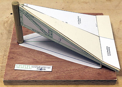
Mike designed the roof sheathing components to fit the trusses, then glued outlines of them to stiff cardboard, and cut them out. We'll need 12 4'x8' sheets of plywood for the sheathing. This photo shows how the pieces will fit. The tiny open triangles at the peak will be covered with small pieces of plywood measuring approximately 2"x4".
The self-supporting truss roof makes it imperative that the eight corner posts are set in precise positions, and that they are plumb and equally spaced. This can be tricky when wrestling heavy 6x6 pressure-treated lumber in 2' holes.
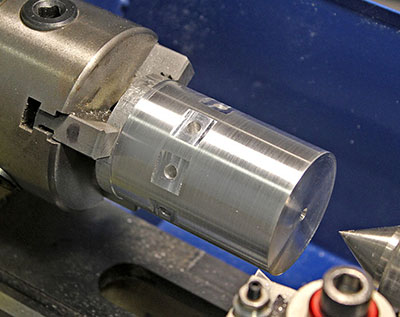
We'll start with a "benchmark" consisting of a ¾" threaded steel rod set in a concrete footer at the center of the shed. Measurements and angles will be referenced to this rod. An aluminum cap with eight radial eye bolts will fit on top of the rod. We will set up a theodolite directly over the rod, and string lines every 45° from the eight eye bolts toward the shed perimeter, staking them exactly in line with the theodolite's crosshairs. This is the aluminum cap with eight holes drilled at precise 45° spacing. The flats were milled and the holes drilled on our milling machine, with the piece held in this same lathe chuck mounted on a rotary table. The piece remains chucked in the lathe so Mike can bore the ¾" center hole.
We will measure the appropriate distance along each line, and bore a 12" hole 24" deep into the earth for each post, using a power auger, then we'll pour a concrete footer in each hole. After additional theodolite measurements plus some calculations, we'll mark and cut each post to the correct length. Then we'll be ready to set them.
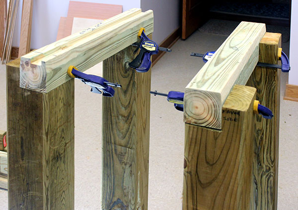
Mike spent a couple of days devising a plan to help us set the posts accurately – see the two drawings below.
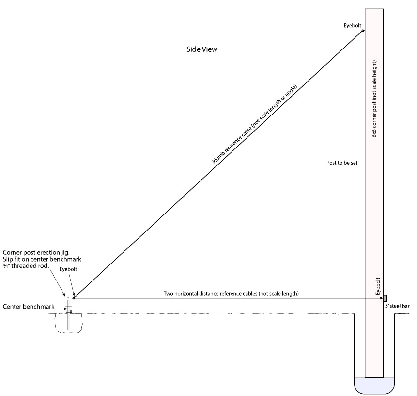
A 3' steel bar will be temporarily screwed to a post, and pre-measured steel cables run from the benchmark cap to eye bolts on the ends of the bar. The cables serve two functions: They place the post the correct distance from the center, and they ensure it directly faces the center of the shed. This latter is vital so the perimeter beam fits the top of the posts correctly, allowing the roof hip trusses to fit properly.
Another cable will run from the benchmark cap to an eye bolt screwed into the post near the top. This ensures the post is plumb in one direction. We'll use an electronic level to plumb it in the other direction. With the first post plumb, we'll backfill the hole with gravel and/or concrete, fixing the post in place.
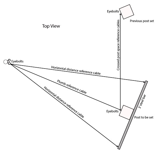
The second post will be set in the same manner, with one additional step. Two cables will be run from the top eye bolt low on the first post to an eye bolt high on the second post. Then a second cable will be run from from the upper to lower eye bolt, forming an X. This will not only plumb the second post, it will also position it the correct distance from the first post.
We'll set each successive post just like the second one, moving the cables and connecting them to the previous post. The plan looks good on paper; we hope it works as well in practice.
By the way, the "pre-measured" steel cables will have turnbuckles so we can fine-tune the length when setting the first and second posts. After that, the cables should ensure all posts are set accurately.
One more note. . . . The threaded benchmark rod will be used later to support, position, and adjust the jig we will use to erect the roof trusses. keep checking this page to see how that goes!
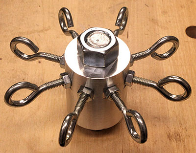
Mike finished machining the aluminum benchmark cap that will anchor one end of the cables we'll use to set the posts. Here it is, with eight eye bolts installed, and bolted to the ¾" benchmark rod.
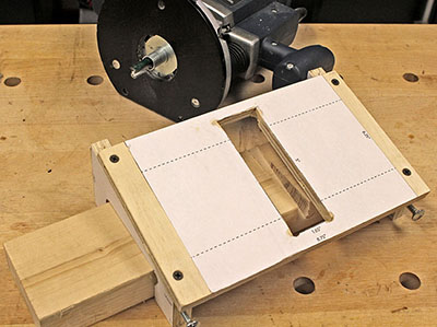
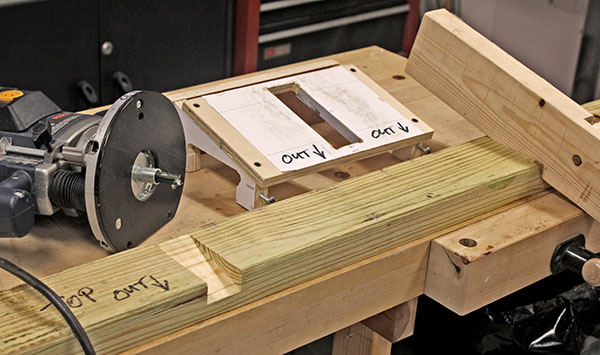
The intermediate roof truss and two jack trusses will rest in slots cut into a 2x4 top plate nailed to the 2x6 perimeter beam. The slot bottoms must match the 3:12 pitch (14.03°) of these three trusses. Mike made a jig from ¾" plywood for the router to cut these slots accurately.
The jig consists of two end pieces that straddle the 2x4, and a top piece with a cutout for a template guide fitted to the router. A ½" straight bit protrudes through the guide, and the depth is carefully adjusted so the bit begins cutting right on the 2x4's top-rear edge, and cuts deeper as the router moves down the jig. The slot is 0.85" deep where it exits the front of the 2x4.
This photo shows the result of one pass of the router on a test 2x4; three passes will rout the full 1½" slot. The two carriage bolts on the front are finger-tightened against the 2x4 to clamp the jig securely in place.
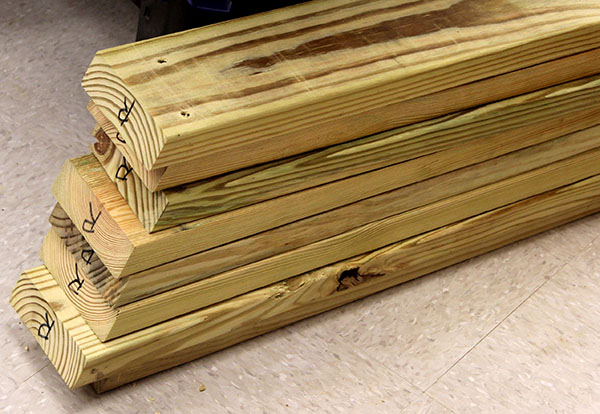
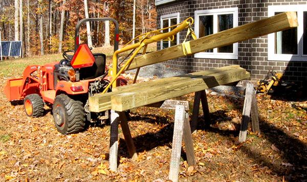
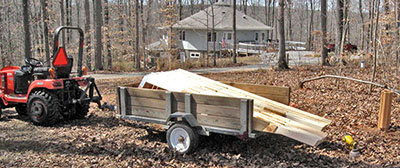
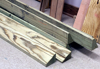
We brought home and unloaded eight 12' 6x6s for the corner posts. Those dudes are heavy! We probably overloaded our half-ton pickup truck, but thankfully it was a short trip from a local lumber yard.
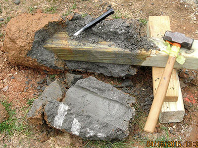
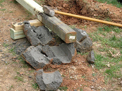
Today we turned our attention to a 275-gallon tank we bought two years ago to hold diesel fuel for the tractor and generator. We pressure-washed the tank interior at the time, and left it to dry for those two years with the open filler holes pointing down.
The tank needed to be moved because it was resting where the shed will be built. In the process of moving it, Mike heard a lot of dry debris sliding inside the tank. He assembled five shop vac wands to reach the tank bottom, and vacuumed some of the debris. But when he pulled out the wand, one joint snagged on the tank opening, and three sections dropped inside the tank!
Mike used the boom pole on the tractor to reposition the tank upside-down so the wand rolled and slid close to an opening, and he managed to snag and retrieve it. Then he taped all five sections together for the next shot at vacuuming.
He turned the tank right-side-up and tipped it with the tractor so the debris slid to one end.
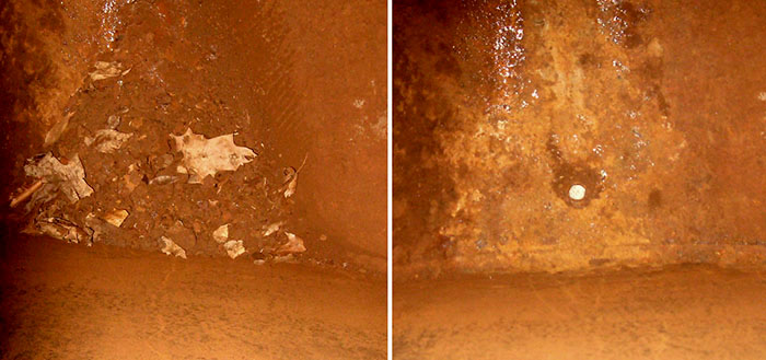
There was a lot of crud in the tank, as you can see in the left photo. The right photo shows the same area after vacuuming. The bright spot in the center is the bottom outlet.
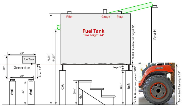
The tank will be installed on 29½" 6x6 legs, high enough for the diesel fuel to gravity-feed into the tractor. The generator will be relocated from its plastic dog house to 20" 6x6 legs inside a shed-roof enclosure behind the tractor shed. This drawing shows the locations of these items and the steps needed to reach the filler pipe on top of the tank.
The drawing below shows the relative heights of the tank, tractor, generator, and access steps but, except for the tank, not their actual locations.
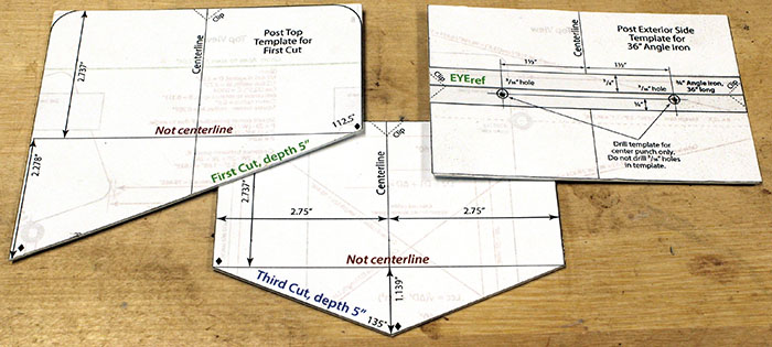
As part of his creating drawings and performing calculations, Mike drew two templates for cutting the post tops to accept 2x6 beams, and a third template to mark holes for attaching the 36" angle iron we'll use with two cables to ensure the post squarely faces the center of the shed. The template drawings are glued to ⅛-inch plastic to make it easy to trace the shape.
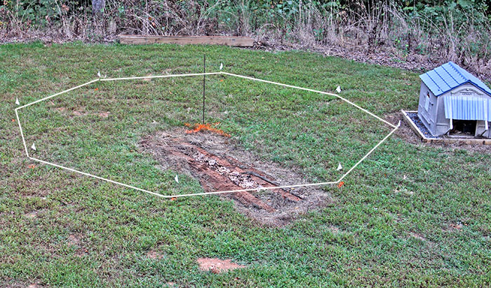
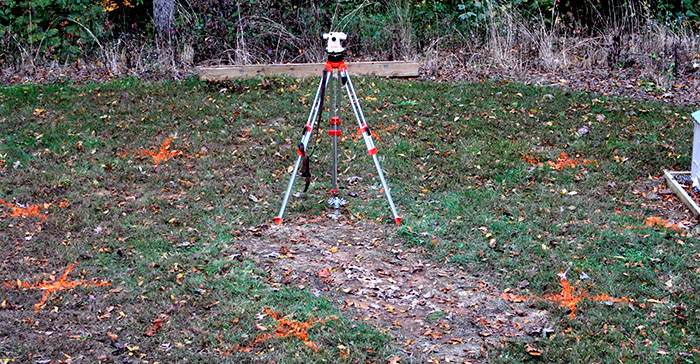
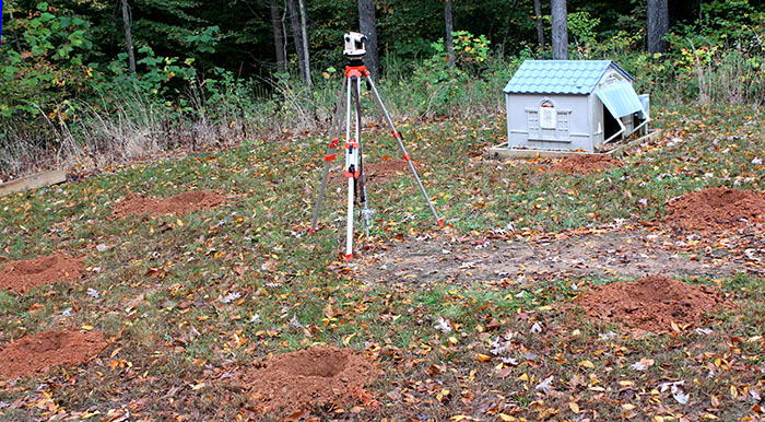
We performed a two-part site survey. First we staked out a rough circle, shifting and re-staking until we were satisfied with the shed location. Then we set up the theodolite in the center and accurately marked the locations of the eight corner posts. This photo shows the center stake and eight white flags (Lowe's was out of orange flags), with the white octagonal outline added in Photoshop.
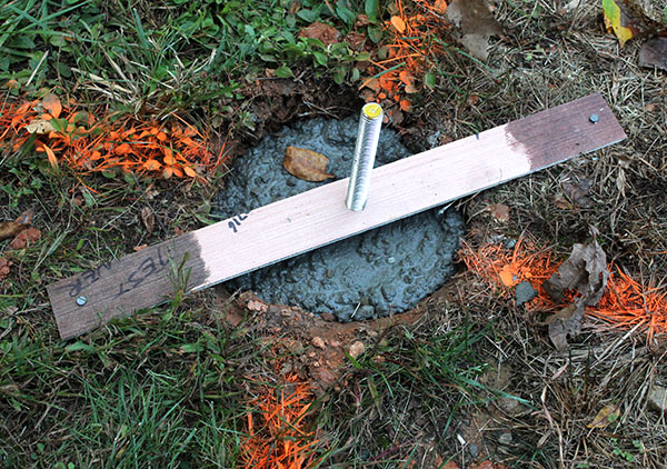
We dug a hole and poured concrete for the center benchmark. This will hold the aluminum cap with eight eye bolts, and will be the reference point for positioning the eight corner posts. It also will hold the 4x4 jig used to erect the roof trusses.
We plumbed the ¾" threaded rod with an electronic level, then nailed the wood strip to the ground to hold it until the concrete cured.
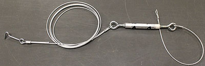
After setting the benchmark, we made the final two of six measuring cables that will help us place posts accurately. This is cable A. The end with the loop goes to an eye bolt on the the center benchmark cap, and the opposite end will hook onto a screw eye on a corner post.
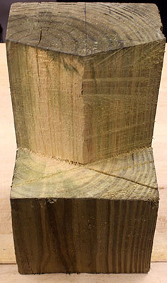
Mike cut 10" off a 6x6, and we used that piece to test making the cuts needed at the top of each corner post. As this photo shows, a post will have a recess to hold two 2x6 beams at a 45° angle. This requires two 22½° cuts 5" into the post from the top, followed by two horizontal slices to create the bottom.
We used a reciprocating saw with a really good blade named The Ax. This blade is 0.062" thick to minimize flexing, which helps it cut straight. The first cut (see the left template here) is 6" long at 22½°, yet it was easy to "steer" this blade along lines on both sides of the 6x6.
We will use this 6x6 cutoff with the theodolite and measuring cable A, above, to mark the locations of holes for the corner posts.
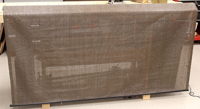
Today we received seven polyethylene roller shades to cover the bay openings. We bought them now to take advantage of a fall sale price. They are 6' wide and 6' tall. Each roller will mount between two 6x6 posts. The shades will hang about 10" above the gravel floor when pulled all the way down.
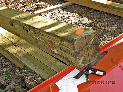
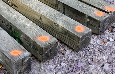
Yesterday and today Mike marked the tops of the eight corner posts for the cuts needed for the perimeter beams. As shown here, each 6x6 post will have a recess to hold two 2x6 beams at a 45° angle. We wanted to mark all the posts first so we can batch the cutting into one operation.
The 12' 6x6s are heavy. Mike wrestled one end onto the tractor bucket, then marked a center line on the end. Next he used the templates to mark the two 22½° lines on the end, then measured and marked the remaining five lines. When done, he sprayed a dot of orange marking paint to show the side that faces outward (the orange wood will be removed during the cutting operation). Then he moved the 6x6 onto some 2x4s on the ground.
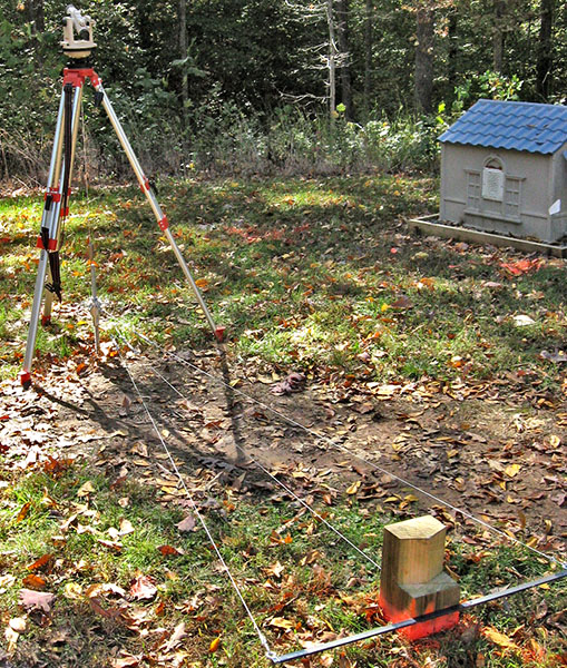
We marked the final locations for the eight corner posts, in preparation for digging the holes tomorrow. First we installed the center benchmark cap with the eight eyebolts, then set up the thedolite with a plumb bob directly over the benchmark. The challange will be to ensure the theodolite doesn't shift over the next several days, while we set the posts – don't bump it, and hope rain doesn't turn the ground to mud.
We used a 6x6 cutoff at the end of a measuring cable to locate each hole. Mike looked through the theodolite to center the post side-to-side at a multiple of 45°. Once accurately positioned, Louise sprayed orange marking paint around the 6x6, then made a large X though the center of the 6x6 outline, so we'll know where to center the hole once the earth auger throws out mounds of dirt.
We discovered we had made three measuring cables too long, so we have to re-make those cables – a minor snag that will cost us only an hour or so.
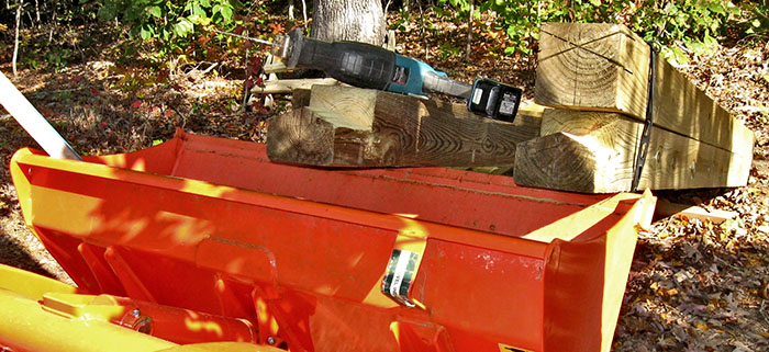
Louise felt under the weather today, so we did not dig holes or re-make cables. Instead, Mike took the tractor to the eight 6x6 posts and used the bucket as a workbench to make three initial cuts on each post top. He used a circular saw for speed, but this does not cut the required 5" into the end grain. so final cuts will be made using a battery-powered reciprocating saw with a heavy-duty blade.
Mike used the cordless reciprocating saw to make the final cuts on four post tops. Alas, the batteries didn't last long enough to cut all eight posts, so the rest will be cut next time, after two days of rain.
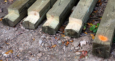
It didn't rain this morning, so Mike made the final cuts on the remaining four post tops. There's nothing like a chest-high workbench! The tractor bucket is ideal for supporting the 6x6s at the right height for cutting.
After two days of rain, today was sunny. We took advantage of the nice weather to dig holes for the eight corner posts.
First we re-made the three measuring cables that were too long. Then we used these cables to re-measure and mark the post locations. This photo illustrates how center cable A sets the post's distance from the center benchmark, and cables B1 and B2 ensure the post directly faces the center. This is important because each post top is cut, as seen above, to accept two 2x6 beams at a 45° angle. If the post doesn't face the center, these two beams can't be securely bolted to it.
With the marking done, we used the power auger to bore 8" holes. Tomorrow we'll enlarge these with a posthole digger, root chopper, and shovel to about 14" diameter, then pour concrete footers.
We spent four hours enlarging the eight post holes to at least 14" in diameter by 18" deep. We ran out of time and energy by late afternoon, so we'll mix concrete and pour footers tomorrow.
Today we spent 2½ hours mixing concrete and pouring footers for fhe eight corner posts. Tomorrow we'll check footer depths with the theodolite, then mark the posts.
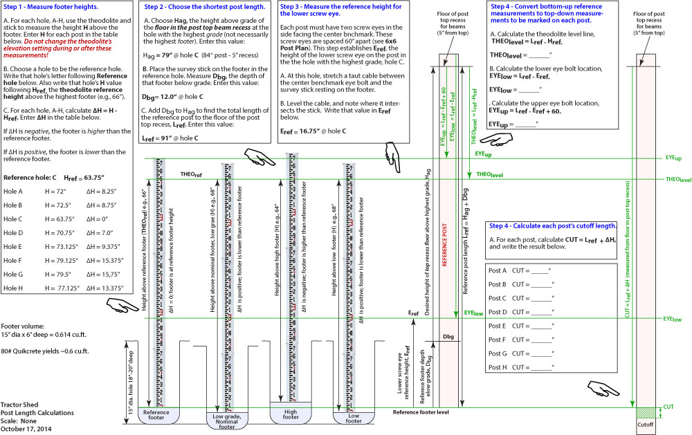
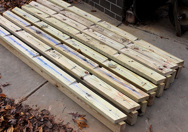
We spent 2½ hours measuring and marking the eight corner posts, in preparation for cutting and setting them in their holes.
The drawing below shows the process. Each post's markings are based on the point, THEOref, where a level theodolite intersects a survey stick resting on the footer. When the post is set, the theodolite should intersect the post at this same spot.
Another important point shows where to cut the bottom of the post to make it the correct length. Since the bottom, not the top, of the post is cut, all our footer-referenced measurements and calculations must be converted to a top-down reference.
In addition to the theodolite reference and the cutting line, we marked points to attach screw eyes for the measuring cables.
We bought eight 8' 2x6s for the perimeter beam, and eight 8' 2x4s for the beam top plates. Each beam will have a 2x4 nailed to the top, which will have three angled slots for roof trusses to rest in.
Tomorrow we plan to set the first post.
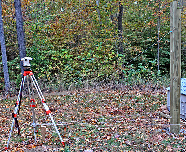
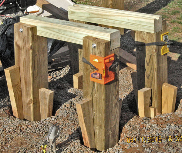
We spent five hours today cutting all eight posts to length and drilling holes for the screw eyes that will hook the measuring cables. We also set the first post, checked it for plumb, and backfilled the hole with gravel. This photo shows four measuring cables in place. They determine the correct distance from the center benchmark, ensure the post directly faces the center, and make the post plumb in one direction.
We used an electronic level to plumb this first post side-to-side, but we'll plumb subsequent posts using crossed diagonal cables back to the previous post. Then we'll double-check with the electronic level. (Note: That didn't work out as well as we'd hoped, so we used two post levels to plumb each post.)
Unfortunately, the center benchmark – a ¾" rod embedded in 20 pounds of conrete – shifted slightly as we tapped the post to make the measuring cables taut. This benchmark must remain centered beneath the theodolite to ensure accurate post placement. Mike made a backstay cable with a turnbuckle. For each post, we'll drive rebar behind the benchmark, and connect the backstay between it and the eye bolt opposite the post being set.
Still developing our work plan, we set the second post. This time, Mike used the boom pole on the tractor to lift the post. Then we swung it vertical, and lowered it into the hole. This is much easier than wrestling the post into the hole by hand, as we did with the first one.
Various measurements between the two posts do not match those on the plan. We'll look into this, and devise a way to ensure each post is placed correctly relative to its neighbor.
Mike discovered the error in his measurement calculations, which he corrected, and we adjusted the measuring cables to the proper lengths.
Using the corrected measuring cables, we adjusted the two posts and checked the spacing with a 1x2 cut to stand-in for a 2x6 beam. We made some minor tweaks to bring the posts to the correct positions and angles, then moved on to the third post.
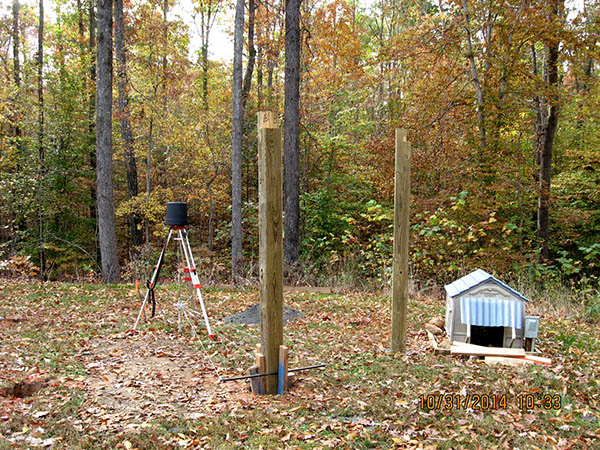
For some reason, the third post was ½" too long, so the theodolite reference line was too high with the post resting on its footer. We removed the post, cut off the excess, then put it back into the hole. (Mike uses the boom pole on the tractor to move the posts.)
Here are the three posts blocked in place. We cut 2x4s cut into long wedges to hold each post on all four sides. Once we install the 2x6 beams on top, we'll remove the wedges and backfill the holes with fine gravel.
It rained today, so we worked in the shop. We cut the eight 2x6 perimeter beams to length, with 22½° beveled ends. We also drilled holes for two lag bolts in each end to attach the beam to corner posts.
Next we must prepare 2x4 cap boards, and nail them to the beams. The caps will have three sloping slots for roof trusses. We want to cut these slots and nail the cap boards to the beams before bolting the beams to the posts.
Mike cut eight 2x4s with 22½° ends to make cap boards for the 2x6 beams. Then he used the router and jig to cut three 1½" sloping slots in each cap to hold roof trusses in place.
Mike nailed the caps to the beams, giving us eight beams ready to install as soon as we set the posts.
We set one more post and installed three beams between them.
Working alone today, Mike set the fifth post and installed a beam between it and its neighbor. Only three posts and four beams left to install.
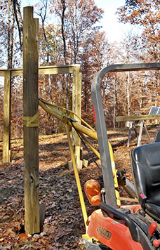
Mike uses the boom pole on the tractor to carry posts to the holes. One end rests between braces on the boom pole so the post doesn't swing as it's carried. Once at the hole, he swivels the post upright and lowers the boom pole to set the post into the hole.
|
|
Again working alone, Mike set the sixth post and installed a beam between it and yesterday's post.
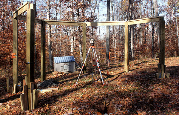
Mike set the remaining two posts and installed their three beams. The shed framing is complete. The next task is to fabricate and install the roof trusses.
Mike lifted each beam on the tractor bucket, then climbed ladders to set each end onto its post recess. He clamped the beam in place while making final adjustments, then drilled holes and installed two lag bolts in each end.
We bought eight 10' 2x4s and eight 8' 2x4s, enough to make four roof hip trusses. We also bought three sheets of 5/8" plywood, enough to make gussets for all 32 trusses. We want to start with just four hip trusses to verify the dimensions, and to test the strength of our design. If successful, we'll buy 2x4s for the remaining four hip trusses, eight intermediate trusses, and 16 jack trusses.
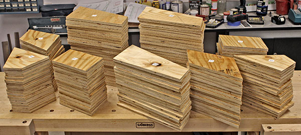
Several days ago we ripped the three plywood sheets into 14 strips of various widths. Then Mike spent three days cutting truss gussets from these strips. The 16 hip and intermediate trusses get four gussets apiece, all on one side, and each of the 16 jack trusses gets one.
Mike used a battery-powered sabre saw and the band saw to cut out the 80 gussets. He stuck a pre-printed identification label to each gusset, so we aren't confused when we need them. Here they are, stacked and ready to use. Unfortunately, there are twice as many gussets as we used. Originally we planned to apply gussets to both sides of a truss, but later decided this was overkill, and the extra nails on the opposite side increased the risk of the 2x4 splitting.
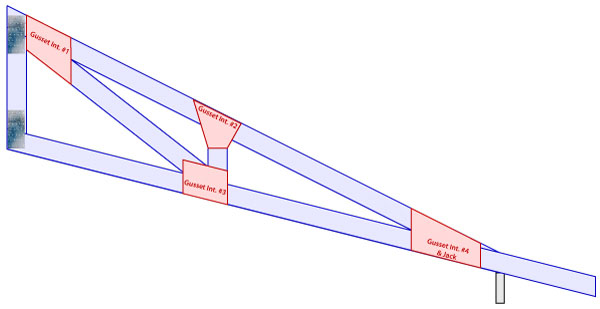
This drawing shows where the gussets will be attached to the trusses, four on each main and intermediate truss. In addition to the 80 plywood gussets, there are 64 steel nailing plates.
Mike cut 2x4s for the first hip truss, and then spent four days figuring out why the pieces didn't fit together. It turns out the long shallow cut on the top chord (top-right in this photo) must be made extremely accurately. Even a tiny fraction of a degree makes a big difference at the wide end of the truss. Mike tweaked the truss cutting jig to make it more accurate, and we concluded that each cut must be measured with a digital angle finder, and re-cut until it is accurate.
Three other pieces depend on accurate chord spacing, so Mike spent a couple of days "solving" triangles using the rule of sines to accurately calculate their lengths.
It turns out that cutting all the angles to fit tightly is not an easy task. Mike cut the final two pieces for the first hip truss, and eventually got everything to fit reasonably well, but it definitely wasn't a cakewalk.
Here is the first hip truss with gussets nailed and glued to one side. This truss will be flipped over to serve as a pattern and measuring platform for the remaining seven hip trusses. The side without gussets allows us to lay the components for the next truss flat on the master for best accuracy.
The steel nailing plates on the vertical chord in the foreground are needed to allow the 16 hip and intermediate trusses to fit side-by-side against the central cylinder. The 5/8" plywood gussets are too thick, so we used thin steel plates instead.
Over three days Mike made three more trusses. The original plan was to glue and nail the wood gussets on both sides of the truss, but now we're thinking that's overkill. We put guessets on one side only, but steel nailing plates on both sides for extra strength at these important joints.
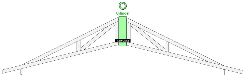
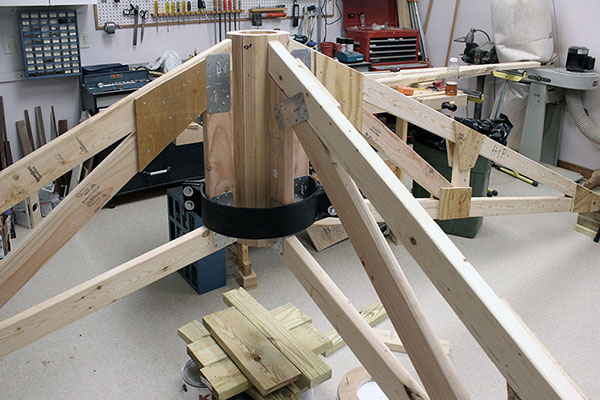
Before we build more roof trusses, we wanted to find out if the design is strong enough. So we raised the center column to the correct height, and clamped three trusses to it (with a short 2x4 standing in for the fourth truss). Then we removed the center support, and the trusses remained standing.
We are delighted that everything works as designed. The trusses showed no sign of weakening when we applied several hundred pounds of weight to two of them. The heavy metal clamp holding the trusses together at the bottom worked flawlessly.
Pictured here are the three self-supporting trusses, and a closeup of the split clamp at the bottom of the vertical chords.
Mike cut the 2x4s needed for the four remaining hip trusses, then assembled two of them.
Mike bought 16 10' 2x4s and 10 8' 2x4s today. The 10' lumber will become the top and bottom chords of the eight intermediate trusses. Mike will cut the angles on these pieces after assembling the remaining two hip trusses. It pays to make all the cuts at once, to eliminate repeated jig and saw angle setup.
Yesterday Mike made the seventh hip truss, and today he made the eighth and final one. These two took longer than expected because one 2x4 on each was twisted. Mike had to clamp everything in place while nailing the gussets, then leave the clamps in place overnight until the construction adhesive cured.
Nevertheless, the hip trusses are built, so tomorrow Mike can start on the intermediate trusses.
We haven't been idle for the past nine days. With all the 2x4s in-hand, Mike cut all the parts needed to make the intermediate and jack trusses. These are:
This photo shows the pieces stacked and ready to assemble into trusses.
Mike has been making two jack trusses per day for a week, and today finished the 15th of the 16 needed. One piece on the final jack truss requires one more cut, but that will have to wait until the remaining seven intermediate trusses are made, and the cutting jig can be changed.
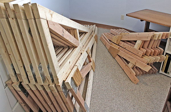
We finished fabricating the roof trusses. Here they are, stacked in a nearby room. Soon we will take them outside, spray them with a wood preservative, then install them on the shed frame. Before doing that, we plan to build 6x6 supports for the generator and a 275-gallon fuel tank.
We need to build a stand from 6x6s for a 275-gallon tank to hold diesel fuel for the emergency generator and tractor.

We laid out the post locations for the fuel tank, but a shaft sleeve on the power auger broke while we were boring the first hole. Fortunately, the manufacturer has replacements, and one is on its way to us. We should be back in operation in a few days, weather permitting.
The factory sent us the wrong part to fix the earth auger. The correct part apparently would require welding, which we can't do, so we sent back the part and bought a new auger on eBay, which arrived today.
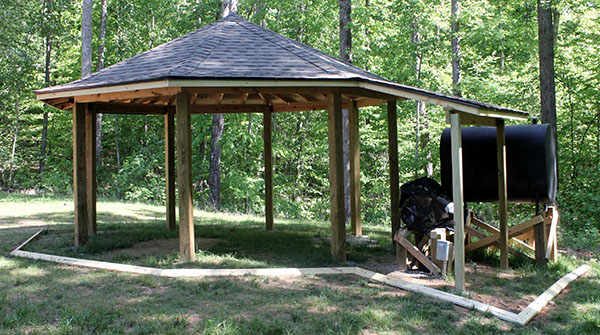
We installed the new earth auger on the power head and bored four holes for the fuel tank stand. Yesterday we placed the 6x6 legs we prepared a couple of weeks ago. Today we set the tank on the legs, bolted it in place, and bolted 2x4 braces to the legs. Finally, Louise dumped concrete mix and water into the holes.
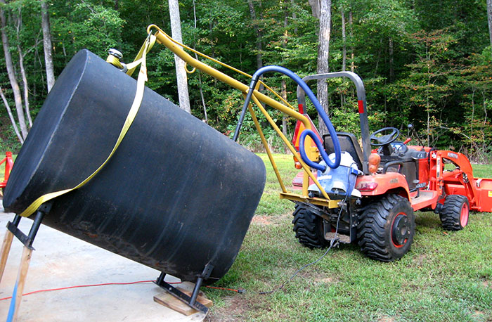
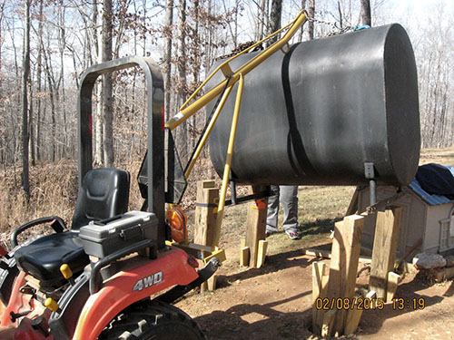
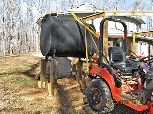
These photos show how we used the boom pole on the tractor to lift the tank 30" above the ground, and maneuver it into the post-top cutouts.
|
|
|
|
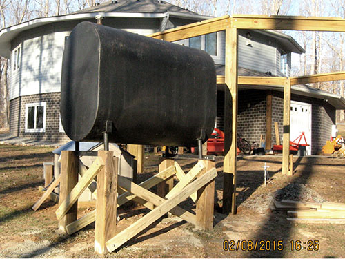
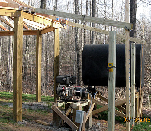
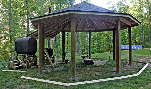
The high view shows the tank location relative to the shed. The tank appears tilted because it is – about 1° toward the outlet end to capture all the fuel in the tank.
The plastic dog house sheltering the generator will be discarded, and we'll build a smaller stand to support the generator. The roof of the adjacent shed bay will be extended over the generator, but not the fuel tank, as shown here.
Mike finished fabricating the steps to allow the fuel delivery person to reach the filler pipe. The 4x4 legs have pointed ends that sink into the ground to prevent the unit from sliding. Even though the steps are not level, they are stable and suitable for the purpose.
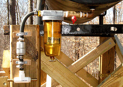
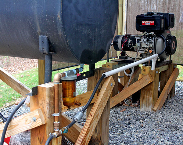
We installed the tank outlet plumbing, and poured several gallons of diesel fuel into the tank to check for leaks. There were none, so we arranged for the oil dealer to deliver 250 gallons of diesel fuel.
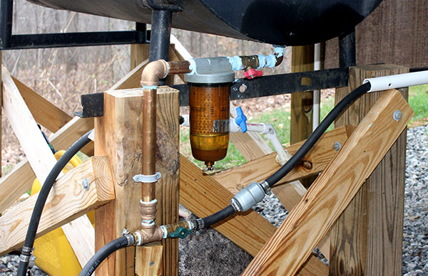
This is the outlet plumbing. Fuel flows through a ball valve, through the primary filter, then through a secondary filter to a tee. A ½" inside-diameter fuel line to the generator will be attached to the right-hand tee outlet, and a similar line with a valve and nozzle to fuel the tractor will be attached to the left-hand outlet.
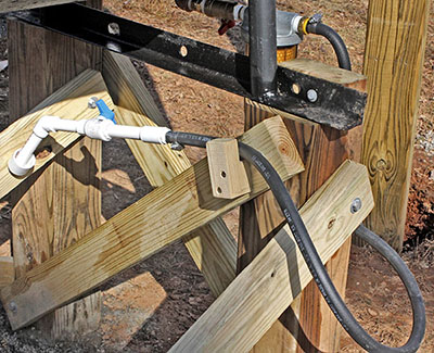
Mike installed a fuel-level gauge on the diesel tank, then attached the hose and nozzle to fuel the tractor. The nozzle comprises ¾" PVC pipe, a couple of fittings, and a ball valve. Mike made two simple brackets to store the nozzle. He also attached the fuel line for the generator, but plugged the end, since the generator is not yet in its final position.
Ten inches of snow prevented us from doing outdoor work, so Mike began work on the jig needed to install the roof trusses. Click here for details on how this will be used.
The ¾" plywood disk is screwed to four "ears" that hold it above the top of a 4x4 post. The central cylinder will rest on top of the disk for the trusses to butt against.
The cylinder must be exactly centered over the 4x4 post, which itself will be centered over the shed's center benchmark. The question is, how do we center the disk which is supported 10" above the top of the post?
The cylinder's 16-point outline is traced onto the disk's top, so we drilled 1/16" holes at six points, and laced monofilament fishing line through them to indicate the cylinder's center. Mike drilled a hole in the center of the 4x4 top, and glued a stiff steel wire into it.
When the glue was dry, we accurately measured from each post top corner to the end of the wire, and bent it slightly in one direction or another until all four measurements were the same. Louise pressed the plywood disk against the supports, and centered it on the steel wire, and Mike fastened the disk to the supports with screws.

Finally – after weeks of snow, rain, and soggy earth – we got a sunny day and the ground isn't too wet to drive the tractor on.
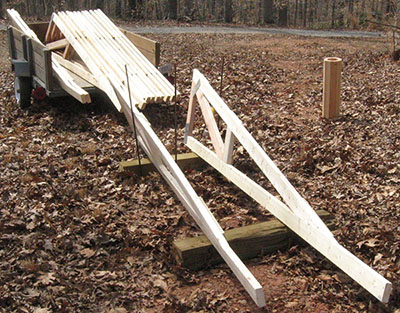
Mike hooked the utility trailer to the tractor, loaded the 16 hip and intermediate trusses, then drove to the observatory area entrance. The trusses were loaded into the trailer are upside-down. Mike sprayed Thompson's WaterSeal on the exposed bottom chords, so they would be mostly dry when ready to unload and flip the trusses right-side-up for the main spraying.
We're spraying waterproofing on the trusses because they are made from untreated lumber. Ultimately, the trusses will be covered by the roof, and not exposed to water, but they will be exposed after being installed, until our contractor arrives to sheathe the roof. We don't want the trusses to absorb water, which could promote rot if trapped under the sheathing.
This photo shows the tractor and trailer with the upside-down trusses drying.
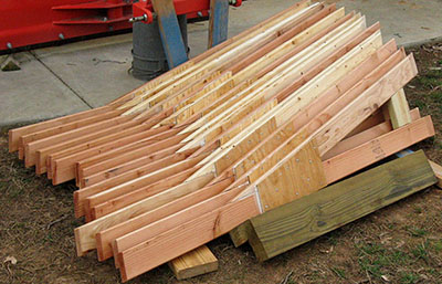
While the bottom chords were drying, Mike set up two scrap 6x6s to support trusses, and three lengths of rebar to keep the trusses upright. He worked on two trusses at once, alternately tipping one, then the other, first against an outside rebar, then against the center rebar. The tilt made it easier to spray the underside of the top chord and angle brace.
Louise arrived home shortly after Mike began spraying the trusses, so she moved the trusses to and from the 6x6s. In this photo, the two trusses to the left in the trailer have been sprayed. Those to the right will be removed in pairs, turned right-side-up, and set on the 6x6s for spraying. This assembly-line setup worked well, and we finished spraying all 16 trusses in about two hours.
The center cylinder standing upright on the ground is drying after being sprayed inside and out.
After yesterday's success with the 16 long hip and intermediate trusses, today we sprayed the 16 short jack trusses, and stacked them near the house to dry. We finished in about an hour.
Mike brought the trailer of hip and intermediate trusses to the family room patio, then stacked them there, sheltered from rain until we are ready to install them. He also moved and stacked the jack trusses in another sheltered location.
We've had four 80-pound bags of concrete mix sitting on the family room patio for months, so today, being dry, we cleaned out the footer holes around four corner posts, and poured the concrete and water into them.
We bought five more 80-pound bags of concrete mix, and used them around the final four corner posts. The next task is to install the roof trusses.
Finally, after all the prep work, we placed the truss erection jig onto the center benchmark ¾" threaded rod (Mike had drilled a 5"-deep hole in the bottom of the post). Four steel guy wires with turnbuckles run to four corner posts to hold the 4x4 post plumb.
This high-angle view shows the post with the truss center cylinder sitting atop the plywood base attached to the post top. Guy wires with orange caution tape are barely visible about midway up the post.
The tall end of eight hip trusses will butt against the center cylinder, with their bases resting on the plywood ring. Each truss will extend through the gap in the perimeter beam above each corner post. Each of the eight intermediate trusses will rest in the center notch in each segment of the perimeter beam, and their wide ends also will butt against the center cylinder, and rest on the plywood ring.
This closeup shows the center cylinder on top of the plywood ring, which is attached to the four arms bolted to the top of the 4x4 post. The cylinder is screwed to the plywood ring to keep it from toppling over as trusses are installed.
As each hip or intermediate truss is set in place, Mike will reach up inside the cylinder with a palm nailer, and drive two short nails through pre-drilled holes into the truss vertical chord. The nails are not structural – they prevent the truss from falling over or otherwise moving during the installation process.
When all 16 trusses are in place, the split clamp will be bolted around their vertical chords to hold them firmly against the cylinder. Then the three screws holding cylinder to the plywood ring will be removed, and the erection jig lowered by turning a nut on the center benchmark ¾" threaded rod. As the jig is lowered, the roof becomes self-supporting – the split clamp holds everything in place.
For peace of mind, the erection jig will remain in place while workers are sheathing and shingling the roof.
Mike carried a hip truss to the shed and sized-up the task of raising it into place. He quickly concluded that standing on an 8' aluminum stepladder wasn't a good idea. We need a scaffold so one person can stand 5' above the ground and position the trusses into place.
After a discussion about how useful it would be to have scaffolding available vs. not buying "more stuff," we decided to spend $200 for a 6' scaffold. Mike drove to a nearby Lowe's and picked it up.
Tomorrow he will assemble it, and hopefully we'll begin erecting trusses.
Today marks a milestone – we began setting roof trusses. We set up the new scaffold with the platform at 5', and Mike climbed aboard. Louise handed Mike a hip truss, then climbed a ladder at the shed perimeter.
Mike set each truss on the erection jig's plywood ring, and Louise secured her end with a bungee cord. Mike wrapped a bungee cord around the truss vertical chord and the central cylinder. Then he used a palm nailer to drive nails through two pre-drilled holes in the cylinder wall and into the vertical chord, to prevent the truss from tipping while more are installed.
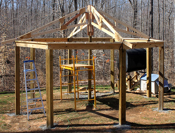
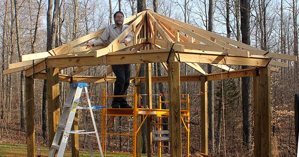
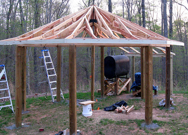
We didn't work yesterday, but made major progress today. We set the remaining four hip trusses and the eight intermediate trusses. Here is Mike taking a break before driving stabilization nails into the final truss.
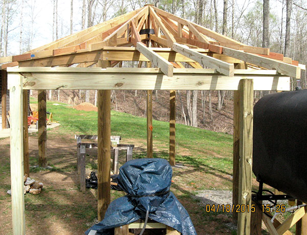
Here's a high-angle shot of the shed with the main trusses in place. The empty slots on the 2x4 perimeter beam cap between the intermediate trusses and the adjacent hip trusses are for 16 jack trusses. Two jack trusses will run parallel to each intermediate truss, and attach about midway to their adjacent hip trusses.
This interior view shows the 16 hip and intermediate trusses resting on the plywood ring, and butting against the central cylinder. The next step is to install the split clamp around the 16 vertical chords, just above the bottom chords.
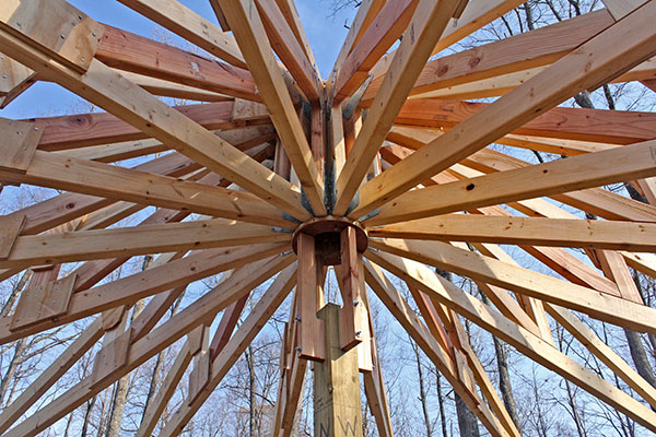
The 16 hip and intermediate trusses are clamped to the central cylinder. It was a struggle, but we got it done.
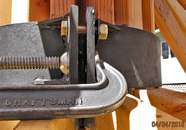
Mike placed the clamp halves around the cylinder and, after much jiggling and jostling, managed to align the holes, and inserted two bolts and nuts with enough threads showing to hold the clamps together.
Then it was off to the other side, where the clamps were widely separated, and didn't want to come together. At Louise's suggestion, Mike used two C-clamps, alternately tightening each to gradually close the gap. Fortunately the holes aligned, and he inserted one bolt and nut.
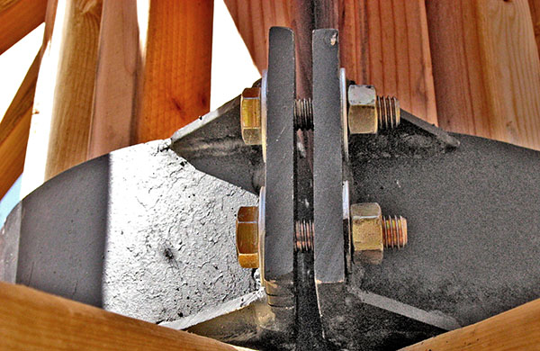
Mike tightened the nut to hold the clamp halves together, removed the C-clamp, then inserted and tightened the second bolt and nut. Next he went back around to the first side. He removed one bolt and used a C-clamp to draw the split clamp together, tightening the remaining bolt as progress was made. Once the ends were close enough, he removed the C-clamp, inserted the second bolt, and tightened both to their final torque. These are grade-8 bolts and nuts for maximum strength.
After clamping the trusses yesterday, today we discovered three that needed shimming – the clamp had lifted their ends free of the perimeter beam. We added the shims, then decided to see if the trusses would remain in place after lowering the erection jig.
Surprise! When Mike put the wrench on the nut that supports the 4x4 post on the center benchmark threaded rod, he found it was already finger-loose.
It turns out that clampling the trusses drew them closer to the center cylinder at the bottom, which raised the cylinder and the erection jig attached to it. The trusses were already self-supporting!
Mike removed the three screws attaching the plywood ring to the bottom of the center cylinder, then lowered the erection jig. Here's the proof we wanted to see – open air between the cylinder and the plywood ring.
We spent four hours installing the 16 jack trusses. These half-length trusses run parallel to intermediate trusses, and attach to hip trusses, one on each side. Here is a shot of the shed with all 32 trusses installed. The roof structure is complete.
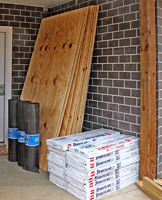
Later we drove our pickup truck and utility trailer to buy a ton of sheathing and shingles, plus a few additional supplies to build a shelter for the generator.
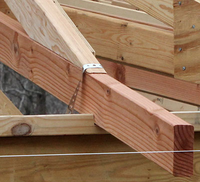
After wasting most of the day expecting rain that never came, this evening we installed steel strapping over the 32 roof trusses. These "hurricane straps" tie the roof to the shed structure so high winds can't lift it off. The trusses are not nailed to the beam so they can move slightly if temperature swings cause them to expand or contract.
As shown on the floor plan, we will extend the shed roof 6' beyond the closed bay, to shelter the diesel generator, which will be mounted on 6x6 posts about 18" high.
Today we removed the plastic dog house, and shifted the generator several feet to make room for two 4x4 posts to support the roof extension. We'll clean up the debris when the ground is dry enough to maneuver the tractor.
This is the stand that will support the generator. The generator's U-channels rest on two 4x4 beams bolted to four 6x6 posts. We need to fabricate the stand components, then bore four holes in the ground and build the stand.
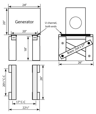
Last night Mike drew the generator stand plan shown above, then cut the pieces and clamped them together to check the fit.
The four 6x6 posts are 39½" long, half of which will be buried in a hole with concrete, so the stand will be about 20" high. The top of each post is notched to hold a 4x4 beam on which the generator will rest.
We slightly tapered the top 1" of the beam sides, and rounded the edges to match the steel U-channels on the bottom of the generator. The 4x4s will be bolted to the side of the post notch.
The slot in the lefthand beam provides clearance for two mounting bolts under the diesel engine. The generator's mounting is elevated, so no bolt protrudes through that U-channel.
We spent more than five hours setting up the generator stand. This involved boring four holes with the earth auger, clearing the holes, placing the 6x6 posts in the holes, and leveling and spacing them all correctly.
The work required a lot of trial-and-error, but we finally got the posts and beams very close to their final orientation. Tomorrow we plan to make final adjustments, then use the tractor to lift the generator onto the stand, add cross-braces, and pour concrete into the holes.
The tapered sticks in the holes next to the posts are wedges we use to plumb posts. They are about 16" long, and hold a post securely in place. We cut them from 2x4s on our band saw. They are extremely helpful.
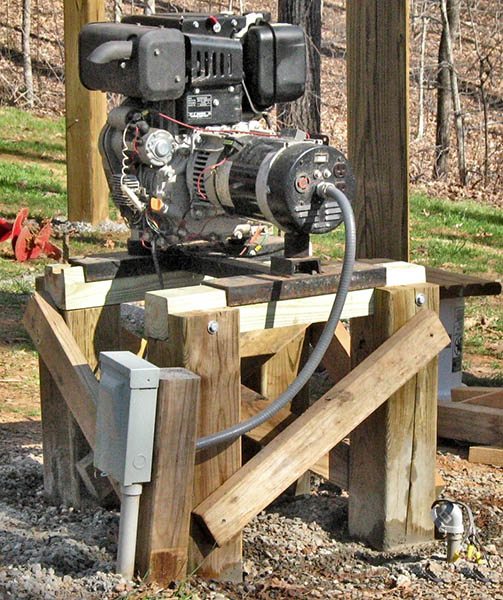
The generator stand is complete, and the generator is sitting on it. We double-checked the post and beam alignment, and tweaked them slightly to make everything plumb and level.
Mike rigged a sling for the generator, and lifted it with the boom pole on the tractor, then carefuly positioned it over the stand, while Louise made final adjustments by hand. This poor-quality photo shows the generator in the sling, just after it was lowered into place.
Our careful measurements paid off – the generator fit perfectly onto the stand. Louise drilled a ½" hole into the beam and post at each end of the U-channel under the engine, then drove two short lengths of rebar to prevent shifting due to engine vibration.
We added bracing on all four sides, then poured concrete into the post holes. We reassembled the electrical connection to the generator, and called the day a success.
We began work on the shed roof extension to shelter the generator. Mike clamped 2x4s to two roof trusses to get an idea where the 4x4 posts should be placed to support the beam the truss extensions rest on.
Later we bolted one post to a 6x6 on the fuel tank stand, and bored a hole in the earth for the other post. We cut it to length, set it in the hole, and added concrete.
This photo shows the two 4x4 posts and the truss extensions with temporary supports clamped above them. Rain is on the way. We will fabricate the beam and cap between the posts, and add the remaining truss extensions when the rain stops.
Oops! Looking over the 4x4 posts we set three days ago, we concluded they were in the wrong locations – they should be closer together and nearer the shed. We decided to space them 6' apart, and 6' from the shed, to accommodate two more of the 6' pull-down shades we're using on the seven shed bays.
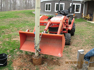
Mike used the tractor to pull up the one post we set last time. This proved to be more difficult than he anticipated, but eventually he got it out, and broke off the concrete. These photos tell the tale.
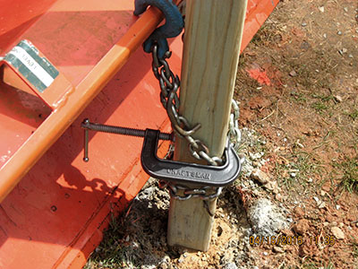
Mike looped a heavy chain around the post and hooked it onto the tractor bucket. A C-clamp on the post prevented the chain from sliding up. |
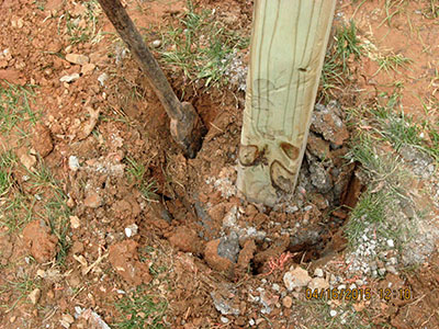
Raising the tractor bucket didn't budge the post. Alternately pushing and pulling on it loosened it a bit, but not enough. Mike pounded a root chopper into the earth around the concrete, then poured in half a bucket of water for lubrication. |
Finally, after repeated upward jerks and rocking the post to and fro, it broke loose. |
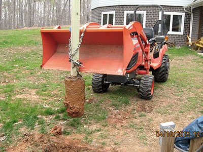
Free! Free at last! |
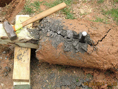
Mike attacked the concrete with a cold chisel and a 3-pound hand sledge. After 15-20 blows, the concrete cracked |
A few more whacks, and the concrete broke apart, leaving only a short length still surrounding the post. |
Success! A couple of blows with an 8-pound sledge hammer directly to the concrete caused it to fall away from the post. |
We finally got it right. After careful measurements, we bored new holes for the two posts to support the shed roof extension over the generator. We plumbed the 4x4 posts – the one pulled yesterday plus a new one – and added concrete to the holes.
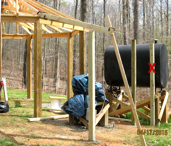
This photo shows the two posts, plus an original post (with the red X) still in the wrong location. It will be unbolted from the fuel tank stand. It is too short to be reused in one of the two holes, so we'll save it for a future project.
A 2x4 truss extension is visible above the near post. This rafter will rest on a 2x4 cap atop a 2x6 beam fastened between the two posts. We used this temporary clamp-up to measure and ensure the posts were set at the correct height.
Blessed with another sunny day, instead of the predicted rain, Mike attached the beam betwen the two posts, and set three of the five truss-extension rafters for the generator shelter.
Even though we had carefully measured the post height yesterday, the planned beam height proved to be too low when the first rafter was clamped in place. So Mike raised the beam one inch to ensure the rafters match the truss lower chords' 3:12 pitch.
Here is a picture of today's work. The 2½ remaining rafters all require special cutting, due to the odd angles involved. Mike hopes to install those tomorrow. (The half-rafter is a short 2x4 that runs from the beam to the angled north rafter, to reduce the open span between two rafters to less than 20")
Mike spent four hours today finishing the generator shelter framing. All the rafters are in place and tied down with galvanized steel straps. Here is a shot after today's work.
We need to nail band boards onto the ends of all shed trusses and generator shelter rafters. Sadly, heavy rain is forecast for the next two days, so we'll have to wait until the ground dries out before we can do that.
The ground was dry after only moderate rain, so this evening we put up five treated 1x4 band boards. Mike made two simple brackets that clamp onto the truss to hold an 8' band board in position while we measure where to cut 22½° end bevels. Once cut and test fit, we nail the board to the truss ends and move on to the next bay. We must stand on ladders for this work, and move them often.
Once the band boards are up and dry weather is forecast, we will call the contractor to install the roof.
We installed only one band board today, over the bay adjacent to the fuel tank and generator shelter. The shelter roof on that side requires a short band board to reach the first rafter, so we spent considerable time getting both to fit. We stopped when it began to rain.
We installed the final two band boards on the shed, then the single band board on the generator shelter. The shed is ready to have the roof installed.
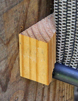
After half an inch of rain, it will be several days before the ground is dry enough for our contractor to install the roof. In the meantime, we ripped four 10' 4x4s into edging for the gravel floor.
The edging, shown by the pink outline in the floor plan, will have a 2½" vertical back to retain the gravel, and a sloping front to provide a ramp for the tractor.
This job turned out to be much more difficult than expected. The table saw blade didn't cut all the way through the 4x4 when tilted the required 25°, which meant we had to flip the 4x4 over and make a second pass. Ultimately we prevailed, using a circular saw instead of the table saw. Some of the pieces turned out different than the plan, but we think they're good enough.
Here is today's work. The two lengths in the foreground are oriented as they will be used. The tractor ramp is in the front, and the vertical gravel retainer is in back. The edging will be "nailed" to the ground with 2' lengths of rebar.
Mike cut three bundles of shingles into 190 12"x12" hip shingles. These shingles are laid up each hip truss, over the ends of the regular shingles covering the flat area between two hip trusses.
What a nasty job! Mike used the table saw for accuracy and speed, but the spinning blade threw granules all over the place. Mike taped a piece of cardboard to the saw sled to protect his face from the flying granules, but they still ended up over a broad area of the shop floor.
Here is a stack of shingles being cut. The sled slides in the table saw's two miter gauge slots. A wooden stop is clamped 12" away from the blade slot.
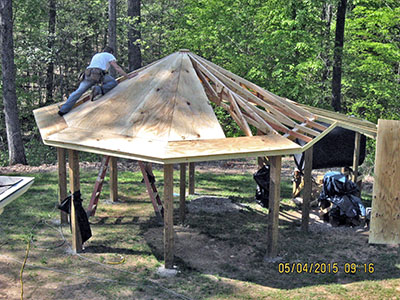
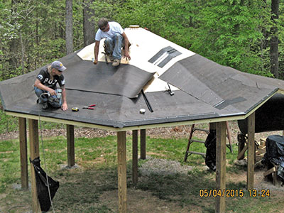
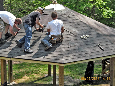
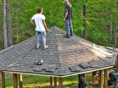
Our contractor arrived with two helpers at 8:30, and they promptly began cutting and nailing plywood sheathing on the roof trusses. They worked all morning and by 1:15, back from lunch, they were stapling tar paper onto the sheathing. By 2:30 they began nailing shingles, which carried them through the afternoon. By 7:00 the roof was complete.
|
|
|
|
Mike lowered the center post an inch or two, and the trusses didn't even whimper as they supported themselves plus 2,000 pounds of plywood and shingles. Not one creak or groan as the post was lowered!
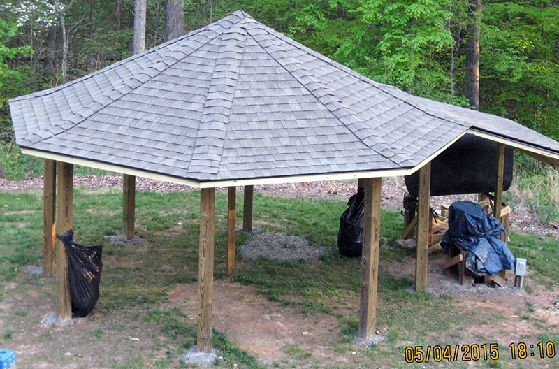
Here is the shed just after the workers left. Tomorrow we'll remove the post and erection jig, which now is loose but trapped on the benchmark threaded rod.
Next job: Clean up the debris, then lay the edging for the gravel floor.
Mike removed the post and erection jig, pulled the concrete center benchmark from the ground, and filled the hole with gravel. The roof is self-supporting, and the shed interior is clear of all obstructions.
in this photo you can barely see the black clamp holding the trusses to the center cylinder. There is plenty of headroom, even while standing on the tractor deck.
We took four large trash bags of roofing debris to the landfill. The shed is ready for the finishing touches.
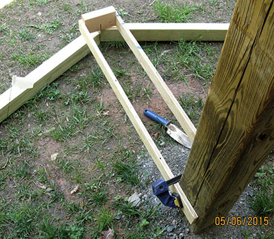
Today we began laying the split 4x4 edging we prepared a few days ago. Mike ran a string around the shed corner posts, measured out 28", and planted marking flags. Then he made a simple jig to "extend" a 6x6 post's face out to the edging. He marked a center line on the jig, and we knew where to position the edging, and where to mark for the 22½° cut.
Here is the jig clamped to a corner post and extending to the edging. Its line indicates we cut and mated the edging correctly.
Each length of edging must mate fairly well with its neighbors, so we have to level the ground under it with a shovel. Once everything lines up, we "nail" the edging in place with two 24" lengths of ½" rebar through holes drilled in the board. We laid only two pieces today because we spent a lot of time setting up and figuring out how to do things.
We laid nearly all the remaining gravel edging today. Only about 21 feet remain, but we need to buy one more 4x4 and rip it in half to finish the edging.
Mike took advantage of some free time before Mother's Day dinner with family, and hung the first pull-down shade on the northeast bay. It was an easy task, but required careful measuring to center the shade between two corner posts.
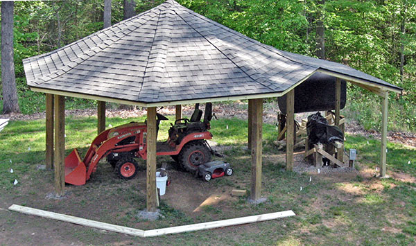
As expected, the 6' shade doesn't reach the ground. The bottom gap will be even larger on the south-facing bays (left, in the photo), because the ground falls away in that direction.
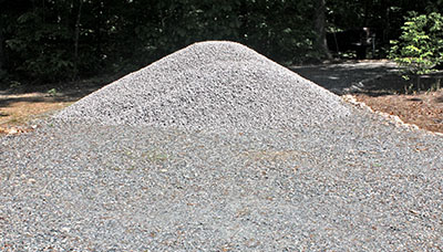
We took delivery of 16.4 tons of #57 stone. It is piled in the driveway, but soon we'll begin reducing the pile. Nearly six tons will be spread on the tractor shed floor. When that project is finished, we plan to build a parking pad for our pickup truck, which will take most of the remaining stone. We'll spread any left over on our driveway.
We took advantage of pleasant 76° sunny weather to finish the gravel edging around the generator and fuel tank. We had to splice the edging with lap-joints in several places, but we got it nailed down. The edging is complete. Tomorrow we will begin spreading gravel inside the edging.
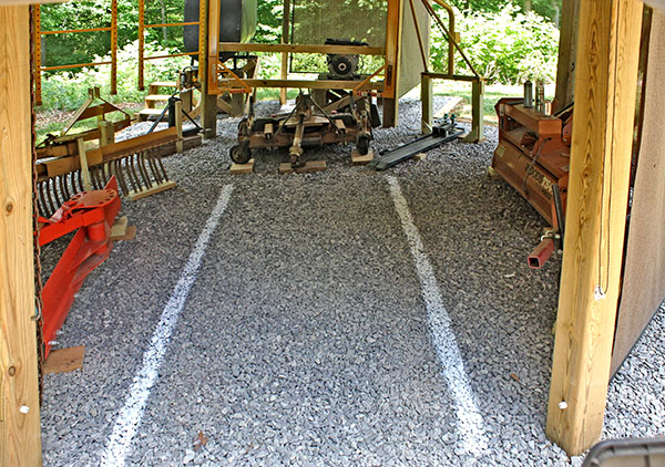
Mike made 20+ trips on the tractor, carrying about 500 pounds of gravel on each trip. He dumped it inside the shed, and Louise spread it with a rake while he went back for another load.
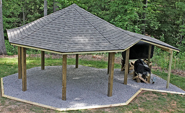
The shed is ready for use. Over the next few dry days, Mike will make "landing pads" for each implement from pressure-treated lumber, and move the implements to the shed.
The gravel floor was the final major construction step. We began to build "landing pads" for the implements, and to install pull-down shades over the bay openings.
There are many photos of the finished shed and implements here. Or click the blue button below to see them.
Yesterday Mike installed three 2x4s across the shed bay facing the generator. We were planning to attach HardiePlank siding to close the bay, but decided this has no benefit. We will use the 2x4s to hang tools or other items.
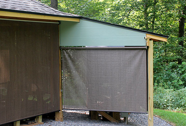
Today we installed pull-down shades on two sides of the generator shelter. The third side is shielded by the diesel fuel tank. Shades were installed earlier on five of the shed's open bays. Two more shades are on their way from the dealer.
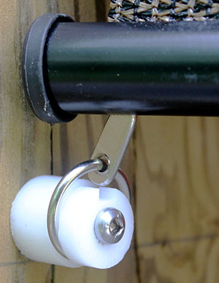
Restraining the pull-down shades proved much more difficult than expected. In 2015 Mike machined 18 "buttons" from Delrin and installed them on shed corner posts at each end of a shade's aluminum tube (left photo). A steel ring slipped over the end of the button, and into the slot (left photo).
Unfortunately, this scheme didn't work well. Wind would blow the shade enough for the ring to slip off the button, and then the shade would whip wildly, causing the plastic end caps on the bottom tube to pop off, and the rings to drop out of the tube slot. One shade even tore when it blew against a sharp corner on a tractor implement.
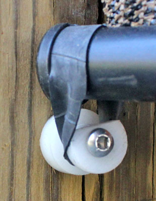
Clearly we needed a better restraint. The next attempt was to cut "rubber bands" from a bicycle tire inner tube. The rubber band looped over the shade's tube and the button (2nd photo). With both ends attached, we raised the shade about ½" to stretch the band. But the rubber bands deteriorated in sunlight, and had to be replaced every month or two. Worse, sometimes they pulled loose in strong wind. Something better was needed.
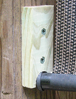
The third attempt was to make wooden brackets with holes for the aluminum tube to hook into. Using a Forstner bit, Mike drilled 1" half-circles in pressure-treated wood brackets, and replaced the Delrin buttons with them. We hooked the ends of a shade's metal tube in the cutout, then pulled the shade tight to maintain tension (3rd photo). This attempt didn't work well because the hole didn't capture the aluminum tube securely, and it came loose fequently.
Finally! The fourth attempt proved to be the charm. Mike replaced the brackets with new ones of a similar design, but cut on a 22½° angle (right photo). Now the aluminum tube is held squarely in the cutout
|
|
|
|
Mike sprayed white lines with marking paint to help guide the tractor when backing into the shed.
Mike mounted a length of 1" PVC pipe between the diesel fuel tank and the generator to protect the flexible fuel line.
We finally cut and installed two triangular panels of HardiePlank on the gable ends of the generator shelter. These panels not only dress up the shelter, they provide additional shelter from blowing rain.
Mike became concerned that the PVC plumbing fittings in the main line from the diesel fuel tank might break from the force of the metal threaded pipe connections, so he rebuilt everything with solid brass pipe and fittings. Our minds are at ease with this new arrangement.
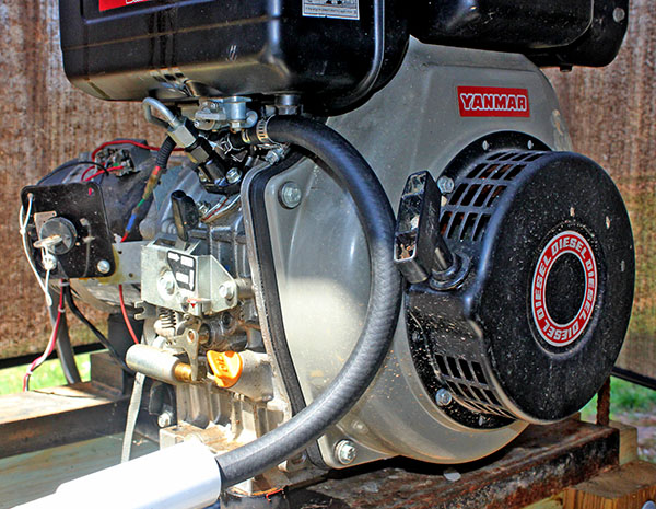
Today we finally plumbed the diesel fuel tank to the generator. The original plan to connect the rubber fuel line to a port on the generator's fuel tank balve did work out because the so-called "port" had no clearance on one side.
Instead, we decided to run the line directly to the same connector the tank was plumbed to. Unfortunately, that tube is smaller than the line from our 275-gallon tank. Mike machined a reducer from Delrin so we could mate the original small tube with our larger line. This photo shows the reducer.
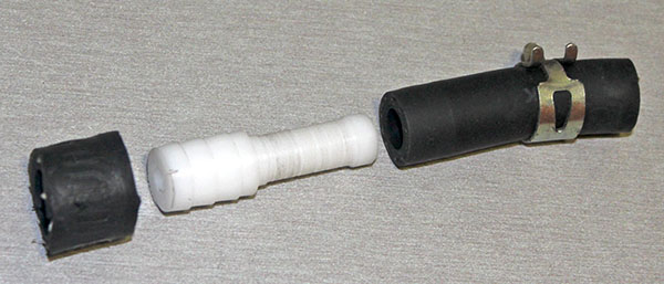
Everything worked out well, and the fuel line fits as if the generator were designed for it. We were concerned that the original tube, the reducer, and our line might not fit in the tight space, but it did.
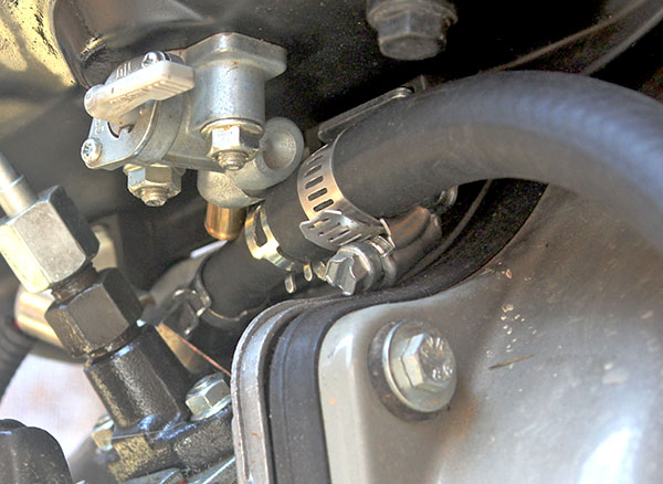
Here's a closeup. We originally planned to drill a hole in the round fitting with the tapered end, but there is no clearance for the hose to slip over it. Originally the short hose with the two spring clamps connected to the brass fitting on the rear of the fuel valve assembly. Now it's clamped onto Mike's reducer.
Updated May 23, 2023